


Hardware components | ||||||
| × | 2 | ||||
 |
| × | 2 | |||
 |
| × | 1 | |||
 |
| × | 1 | |||
| × | 1 | ||||
 |
| × | 1 | |||
 |
| × | 6 | |||
| × | 1 | ||||
 |
| × | 1 | |||
| × | 1 | ||||
Software apps and online services | ||||||
| ||||||
Hand tools and fabrication machines | ||||||
 |
| |||||
 |
| |||||
This is the list of the main steps to create the fountain in a bottle. The steps are described in a sequential order, but most of the steps can be done in parallel.
1. Print all the 3d templates
2. Build the two light sets
3. Create the circuit and connect the components
4. Create the submerged motor set
5. Upload the code to the Arduino
6. Final setup (Insert the submerged motor set in the bottle, Glue all sets on a board for the final layout).
7. Play with it
1. Print the 3d templatesFor these 3d templates, you can find the.stl files on the Attachment section.
The first three items are enclosures to house and protect the electric devices, while the remaining are support items to sustain and make the artefact usable.
- 2x HC-04 holders
- L298N (upside and downside)
- Arduino enclosure (upside and downside)
- 2x Fiber Holders
- fountain disk upper side
- fountain disk down side
The light system is based on two led RGB and a set of optical cables.
The first step to build them, is to take the 2 RGB LEDs, solder each pin with the electric cables, cover each one with a heat shrink tubing. This allow to be more compact and avoid any short cut.
The second step, is to take the optical fibre cable, and cut it in 9-10 strings of about 10 cm each.
Then, join a heat shrink tubing together with the led as shown in the picture below.
The third step is to position the optical fibers on the holders, as shown in the pictures below.
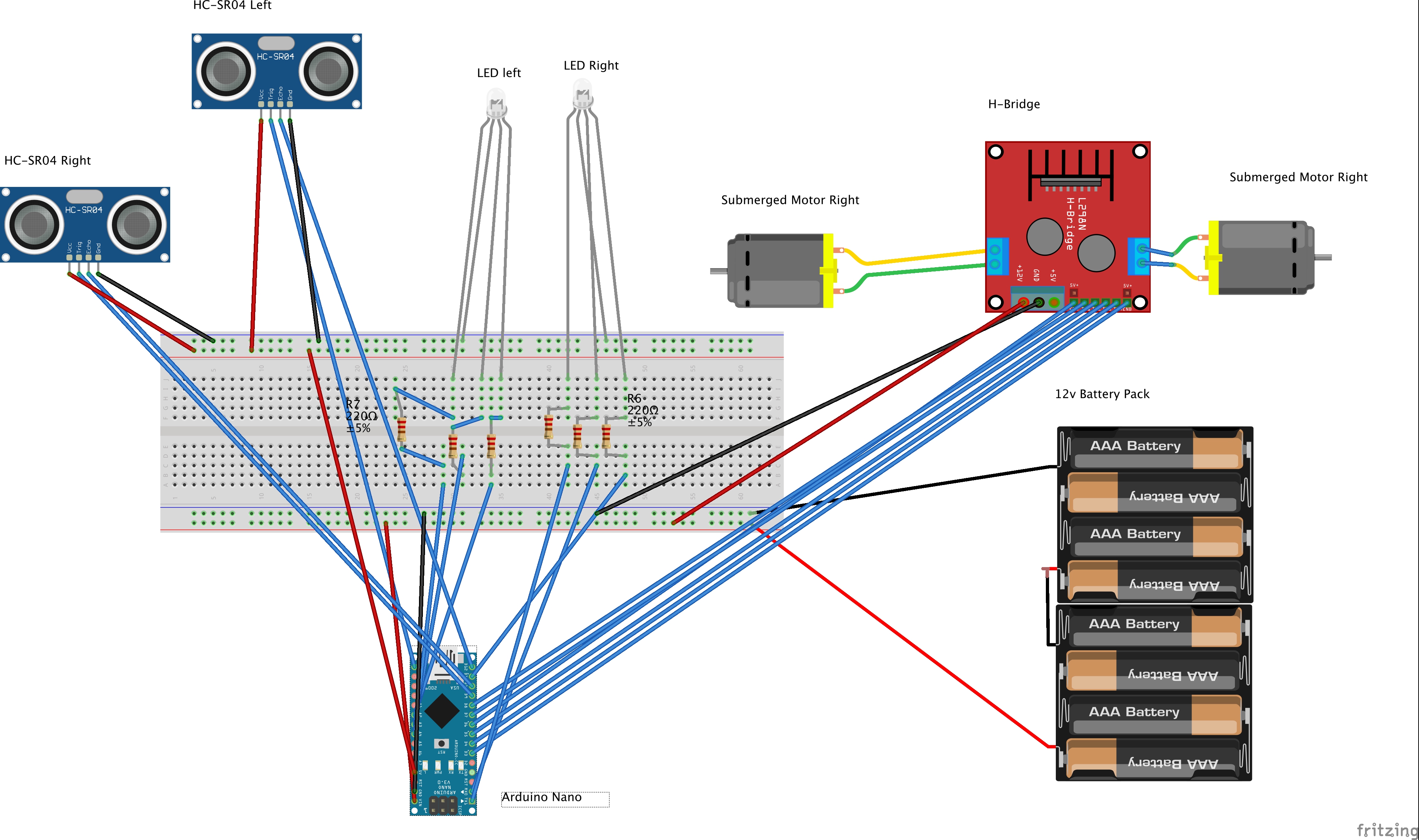
The electric circuit hosts all the 6 resistances needed for the 2 LGB LEDs and most of the connections related to the power (5v and Ground).
The connections shown of the picture, related to the prototype board, have been replicated on the circuit on the two pictures bellow.
The remaining components are connected directly to the Arduino nano.
The two submerged motors are coordinated by a L298N dual H-bridge (connections are shown on the previous circuit diagram).
The external power for the L298 is provided by the external batteries, the PWM (Pulse Width Modulation) are provided by the Arduino board and the four bridge's outputs are connected to the two submerged motors. (as shown in the picture below)
This was one of the most challenging part of the project. The submerged structure needs to keep the two motors horizontal separated at a given distance and a given angle, it needs to be stable at the bottom of the bottle, and last but not least to be waterproof.
The structure is based on two disks, (both the 3D.stl files are on the attachment section). The two disks and the submerged motors are glued together, using a hot glue. Then, a 5 mm foam is attached and glued around the two disks. with the aim to create a buffer and a cohesion with the bottle. The foam layer force the set to remain firm attached to the bottle and stable while operating.
The images below show few details of the submerged motor set.
The code for the Arduino is available at:
https://github.com/EnzoCalogero/Funtain
6. Final setup (Insert the submerged motor set in the bottle, Glue all sets on a board for the final layout).To insert the submerged engine set on the bottle, you need first to cut the top of the bottle, and then create a hole on the side of the bottle for the engines cables.
Once the set is inside and the cables have been inserted, the next step is to seal the hole on the bottle and make the sealing waterproof. I used a proxy glue to seal the hole.
The two final steps are to test that system is waterproof, and glue all the elements together in a board as in the picture below.
Then, the final step is to play and enjoy :-)


_t9PF3orMPd.png?auto=compress%2Cformat&w=40&h=40&fit=fillmax&bg=fff&dpr=2)


_3u05Tpwasz.png?auto=compress%2Cformat&w=40&h=40&fit=fillmax&bg=fff&dpr=2)
Comments