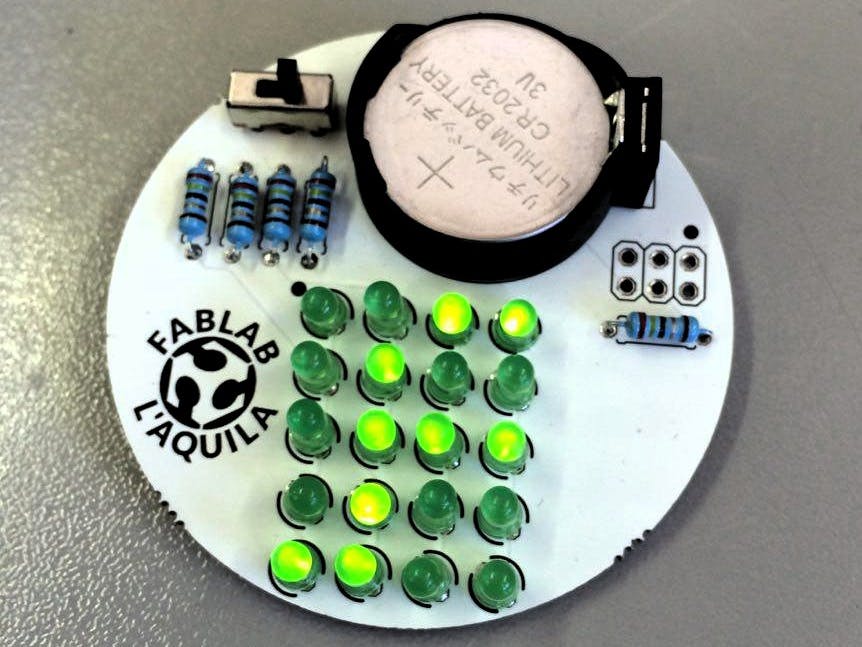
Build a cool LED matrix badge with a custom sliding text string, using a dirty cheap microcontroller (the project is built around the ATtiny13 but if you have other spare ATtinys it will work fine) and other common components. There is a proposed PCB you can order, but the full sources are provided so you can make one on your own.
Assembly instructions (after each step cut the remaining part of the pins)
- First, solder the ATtiny as it's the only SMD component, pay attention to the small circle, thi is the first pin. Start soldering only one pin to keep things simple if you need to move the component, when it's in place you can solder the other pins.
- The large solder pad is made for a hook, so you can wear the badge, but you can otherwise solder a ring made of solid wire to use it as a pendant.
- If you don't have a switch, you can use a piece of strip connector and a jumper, always keep in mind the larger solder pads, make sure they don't touch the switch metal frame.
- Place the battery holder on the top side and solder it, pay attention to the drawing orientation.
- Place the resistors on the top side, bend the pins to keep them in place while you solder them.
- The same (bending the pins) applies to the LEDs, the polarity is marked by a dot on the left-top corner of the matrix, the shorter pins (cathodes) should be orientated towards this dot.
- DON'T insert the battery!
Programming preliminary operations:
- In case you want to use and Arduino as the programmer, you have to upload the programmer sketch first: File->Esamples->11.ArduinoISP->ArduinoISP. Set the upload port in Tools->Port and the right board (Arduino/Genuino UNO), then upload the sketch. Once done you can close the window.
After the programmer choice:
- Open the IDE settings (File->Settings) and paste the URL below in “Additional URLs for the board manager”, then click “OK”:
- https://mcudude.github.io/MicroCore/package_MCUdude_MicroCore_index.json
- Open the Boards manager (Tools->Board->Boards manager), search and install the “MicroCore” package.
- In tools, select the right options. Board: “ATtiny13”; Clock: “1.2MHz internal oscillator”; BOD: “Disabled”.
- In tools, select your preferred programmer, if you are using an Arduino select “Arduino as ISP”.
- Connect the programmer and the badge, the small dot near the 6-pin connector is the first pin (MISO), see the photos for alternative connections.
- In tools hit Burn the bootloader (actually it's not a true bootloader, just AVR fuses), you should see some LEDs flashing, if you don't encounter any problem you can go ahead.
- Download the Github repository in the links below, the sketch is located in the "ATtiny LED badge" folder.
- Open the sketch with the Arduino IDE and edit the text between quotes at your will.
- Upload the sketch, you should see some LEDs flashing, if the Arduino IDE doesn't throw any error you can go ahead.
- Now you can insert the battery (writings outside!) and enjoy your customized LED matrix badge!
Troubleshooting:
- If you're having problems burning the bootloader or uploading the sketch, the cause could be addressable to a faulty programmer connection, but most probably the issue is related to the ATtiny13 solder joints.
I you have any other problem don't hesitate to leave a comment!


_ztBMuBhMHo.jpg?auto=compress%2Cformat&w=48&h=48&fit=fill&bg=ffffff)


_3u05Tpwasz.png?auto=compress%2Cformat&w=40&h=40&fit=fillmax&bg=fff&dpr=2)


Comments
Please log in or sign up to comment.