


Hardware components | ||||||
| × | 1 | ||||
 |
| × | 1 | |||
| × | 15 | ||||
 |
| × | 2 | |||
| × | 1 | ||||
During the construction of the Sakura Densya, I noticed that the LEDs were insufficient for my liking, so I set about adding a few more LEDs here and there during the assembly.
I used SMD LEDs specifically designed for model building, which are already soldered onto fine enamel wires, allowing them to be well concealed within the model. The wires I soldered were 20cm long; if you can find ones with longer pre-soldered wires, feel free to use those. Extending the fine enamel wires afterward can be quite fiddly.
Additionally, I highly recommend using UV glue when placing the wires.
I designed my setup so that I can continue to use the included touch-sensitive sensor, and I can control the different LEDs independently since it wouldn't make sense to have all the LEDs on at the same time.
I solved this by incorporating an infrared receiver into the front, activating different scenes depending on the signal received. The sensor at the front, originally used to switch currents for the two organic LEDs, is now only used in my setup as a signal indicator so that the Nano knows whether the light should be on or off.
You can certainly adjust the number of LEDs to your liking, but I wouldn't recommend adding too many more than I did, as it's already quite a lot.
Step1:Trambarrier
Build your model until you reach step 6. At this step, you should assemble the tram barrier. Do this as described in the instructions, except for the backside of the mast. The whole thing should then look like this:
Now take a 6mm wood drill bit and drill approximately 2mm into the center of the red areas on the barrier signal. Additionally, drill a 2mm hole through the signals at their centers.
Then, pass the LED through the hole and glue it in place as shown in the picture. Afterward, you can attach the 3D-printed cap.
Turn the barrier around now and lay the wires as seen in the picture, then carefully glue them. After that, the back of the barrier can be glued on.
Step2:Train
Continue building according to the instructions until you reach Step 10 and have completed the small train. Here, I've glued on two more LEDs. One above the driver and one at the rear for the passengers. Since the top part of the train is easily removable, it's convenient for attaching them here.
Continue building until step 11, once the track is complete.
Step3:Windows
Continue following the instructions up to step 21. Before you glue the upper window, insert two LEDs there. I placed these on the left inside the windows so that the windows are indirectly illuminated.
Then place the cables in the bottom right corner and stick the window on.
Bonus:Illuminated sign
The keen observers see another cable in the picture coming from below. I also placed an LED in the small roof of the sign.
Now
continue to step 25. Before you insert the right wall, we'll add a total of 4 LEDs under the windows. Two at the top and two at the bottom.
To shield the light from the two floors a bit from each other, I glued small pieces of wood over the lower LEDs. Additionally, I attached thin, light paper to the lower door and the small bookshelf in the front, which still allows the light to pass through but prevents seeing through it to better hide the wires.
The next step is to install the sensor. I now use the sensor solely to send the signal on or off to the Nano. Therefore, we don't need the battery compartment or the red wire that would originally lead to the LEDs. As you can see in the picture, I have shortened it a bit, so it won't be in the way. Install this as described in the instructions.
During the installation, I also attached the infrared sensor, leading it directly to the bottom right corner on the underside.
As a final additional LED, I've also glued one under the bridge.
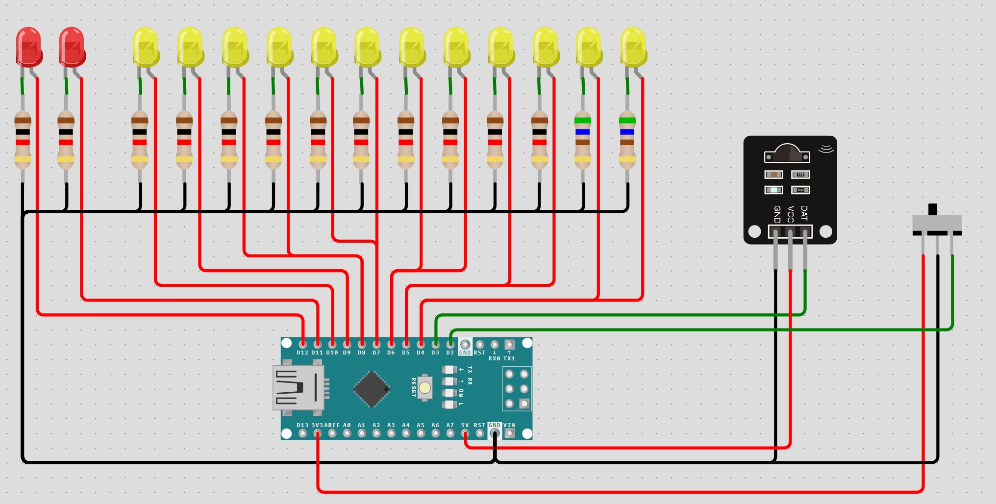
I started with the wiring after step 29. For this, I placed the Arduino Nano on a perforated board. Additional components required here are just a few resistors. Each SMD LED came with a 1kohm resistor. Since I couldn't find specifications for the two standard LEDs included, I opted for 560 ohm resistors for these LEDs. Since I installed a total of 12 SMD LEDs and 2 standard LEDs, this means that 12 times 1kohm and 2 x 560 ohm resistors need to be connected to the Nano's ground.
For control, I connected the lights of the original LEDs on the track in the window top left, the window top right, and the window bottom right in series. Therefore, out of the total 14 LEDs, we need to control nine light sources, ideally via one digital pin. We need another digital pin for the infrared sensor and one for the touch sensor. The Vin of the infrared sensor connects to the Nano's 5V. Since I also couldn't find specifications for the touch sensor, I connected it to 3.3V, which works perfectly.
I placed the connections of the digital pins on the edge of the perforated board with some distance between them, which significantly facilitates later soldering.
I 3D-printed a plate to fit the perfboard so that I could glue it to the underside, then I soldered everything. Since some of the enamel wires were too short to reach the Nano, I had to extend them, which was a bit fiddly.
The pictures here, I believe, say it all. Ultimately, the important thing is just that you can't see the cables from the front. What also worked well here with a bit of glue. Only behind the track could you see a tiny bit of a cable, which is why I also stuck some of the white paper over the cables there.
I drilled holes at inconspicuous spots for the cables to pass through to the underside.
The circuit diagram itself is quite straightforward, as you can see in the attached diagram. In the diagram, the toggle switch is our touch sensor. Here, connect the side that was originally at the battery compartment to GND and the red side to 3.3V. The black cable of the output goes to D3.
Therefore, wire everything accordingly. For the LEDs that are connected together, I soldered the 5V side wires together early on and ran them as a single wire to the Nano. The GND side, of course, needs to be individually wired to the Nano.
The most important thing here is to solder the LEDs to the correct resistors.
The order in which each LED is soldered to which digital pin is basically irrelevant; this can be easily organized later in the code.
Lastly, you just need to arrange the cables one more time so that following the instructions allows you to attach all the remaining parts to the model.
Last Step: The CodeThe code is kept quite simple. My programming works so that when the '0' button on the remote control is pressed, all lights are turned off. I have programmed different scenes on buttons 1-4. You may need to experiment a little, as the order of your LEDs might be different. Feel free to add more scenes here. Additionally, you can turn off the lights using the button at the front. When turning off, the scene is remembered, and if you turn the lights back on, the last scene activated will be reactivated.
Final result:Originallight:
Scene1:
Scene2:


Comments