Nowadays, the problem of wasting water is a very big problem and water is starting to become a scarce commodity.
In the European Union, more than half of the population lives in communities of more than 150, 000 population equivalent (PE), generating a daily amount of 41.5 million m3 of wastewater. For that reason one, of the big challenges for smart cities of the future is to reduce the waste of water in urban areas.
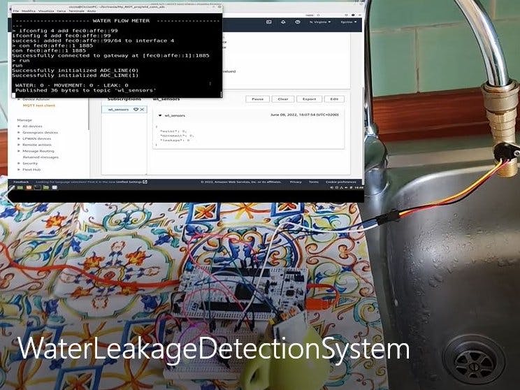
The system proposed here aims to detect a leak of water in a tap and alert someone nearby via an acoustic signal who can then close the tap and stop the leak.
The system monitors the water flowing out of the tap by means of a water flow sensor and movement is detected in front of the tap via the PIR sensor. If water is measured flowing through the tap, but no movement is detected in front of it, the system determines that there is a leak and a buzzer is activated. In order to turn off the buzzer, the leak must be stopped by closing the tap.
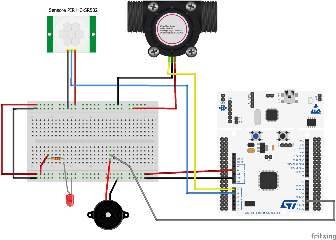
DeviceThe physical device is composed of:
- Board Nucleo-F446ZE: This is the main board of the device. It is connected with the breadboard and reads the data collected by the two sensors.
- PIR HC-SR501: The role of this sensor is to detect any movement near the tap. It is connected to the adc input pin A1 of the nucleo board.
- Water Flow Sensor: This sensor detects whether water is flowing out of the tap. It is connected to the adc input pin Ao of the nucleo board.
- Active buzzer: Activated when a leak is detected. Connected to the out pin D2 of the nucleo board.
- Generic Led: Always on to notify that the system is working.
Enable the adc line for the Nucleo-F446ZE
The board Nucleo-F446ZE does not have the adc lines enabled by default. Therefore, we need to add code in the files Makefile.features and periph_conf.h to enable them.
By adding the following line to the file Makefile.features, we add the feature "periph_adc" that we will later include in our Makefile to use the adc lines:
FEATURES_PROVIDED += periph_adcFinally, we need to configure the pins A0-A5 as adc channels. In order to do so, we need to add the following lines to the file periph_conf.h:
static const adc_conf_t adc_config[] = {
   {GPIO_PIN(PORT_A, 3), 0, 3},
   {GPIO_PIN(PORT_C, 0), 0, 10},
   {GPIO_PIN(PORT_C, 3), 0, 13},
   {GPIO_PIN(PORT_F, 3), 0, 9},
   {GPIO_PIN(PORT_F, 5), 0, 15},
   {GPIO_PIN(PORT_F, 10), 0, 8},
   {GPIO_UNDEF, 0, 18}, /* VBAT */
};

#define VBAT_ADC            ADC_LINE(6) /**< VBAT ADC line */
#define ADC_NUMOF ARRAY_SIZE(adc_config)The architecture of the system is shown in the figure above and is composed of:
- BoardNucleo-F446ZE: Collects data from the sensors and sends them to mosquitto rsmb through MQTT-SN protocol
- Mosquitto RSMB: Act as a MQTT-SN broker, its role is to forward the incoming MQTT-SN messgaes to Mosquitto MQTT broker through MQTT protocol.
- MQTT-SN/MQTT Transparent bridge: Act as a bridge between Mosquitto rsmb and AWS MQTT broker. All the messages handled by the transparent bridge are MQTT messages.
- AWS: The cloud part is developed using Amazon Web Services. Here the messages containing the data collected by the sensors are received, the data are stored in a dynamoDB table and they are available through REST API calls.
- Front-End: Very simple web-dashboard showing the 15 most recent data that are presented in a table and also plotted in charts.
To set up the virtual network interfaces, we need to install the Mosquitto broker and clone the Mosquitto RSMB repository to use it as MQTT-SN broker.
To create the IPv6 vistual interfaces we can use the tapsetup utility given by RIOT. In order to be able to connect the board to the tap bridge we need to assign to it a local IPv6 address as follow:
sudo .../RIOT/dist/tools/tapsetup/tapsetup
sudo ip a a fec0:affe::1/64 dev tapbr0
Now we can start Mosquitto which will act as MQTT-SN/MQTT transparent bridge. With the following command we will start Mosquitto using as configuration file the file my_local_bridge.conf, that you can find in the conf directory in the project github repository. Just to be safe we will execute the command to stop the Mosquitto Service prior to running the new instance of Mosquitto.
service mosquitto stop
mosquitto -c .../conf/my_local_bridge.conf
At this point the transparent bridge is set up and we can start Mosquitto RSMB MQTT-SN server. Put the file rsmb-config.conf located in conf directory inside the folder mosquitto.rsmb/rsmb and execute the following command:
cd .../mosquitto.rsmb/rsmb
./src/broker_mqtts rsmb-config.confThe main program is a c program written to run on top of RIOT-OS and is organized as follow:
Network Functions:
Set of functions needed to use the virtual network environment using the ethos RIOT module to use the virtual IPv6 network created using the tapsetup interface, and emcute RIOT module to send MQTT-SN message to mosquitto rsmb.
On the make file we need to import all the modules needed to handle the IPv6 connection and set all the parameters to use the ethos interface:
# Include packages that pull up and auto-init the link layer.
USEMODULE += gnrc_netdev_default
USEMODULE += auto_init_gnrc_netif

# Specify the mandatory networking modules for IPv6
USEMODULE += gnrc_ipv6_default
USEMODULE += gnrc_icmpv6_echo
USEMODULE += stdio_ethos
USEMODULE += gnrc_uhcpc

# Address of device
IPV6_PREFIX ?= fe80:2::/64
CFLAGS += -DCONFIG_GNRC_NETIF_IPV6_ADDRS_NUMOF=3

# Default to using ethos for providing the uplink when not on native
UPLINK ?= ethos

# Configure ethos parameters
ETHOS_BAUDRATE ?= 115200
CFLAGS += -DETHOS_BAUDRATE=$(ETHOS_BAUDRATE)
# Ethos/native TAP interface and UHCP prefix can be configured from make command
TAP ?= tap0
host-tools:
$(Q)env -u CC -u CFLAGS $(MAKE) -C $(RIOTTOOLS)

# Configure terminal parameters
TERMDEPS += host-tools
TERMPROG ?= sudo sh $(RIOTTOOLS)/ethos/start_network.sh
TERMFLAGS ?= $(FLAGS_EXTRAS) $(PORT) $(TAP) $(IPV6_PREFIX) $(ETHOS_BAUDRATE)
Now, in the main program we need to include all the headers needed to use the network modules, define an id to assign to the systems emcute connection, and also we need to initialize the stack to exchange messages:
#include "msg.h"
#include "net/emcute.h"
#include "net/ipv6/addr.h"

#ifndef EMCUTE_ID
#define EMCUTE_ID           ("gertrud")
#endif
#define EMCUTE_PRIO         (THREAD_PRIORITY_MAIN - 1)

static char stack[THREAD_STACKSIZE_DEFAULT];
static msg_t queue[8];
static emcute_sub_t subscriptions[NUMOFSUBS];
Now we have to implement a function to connect the board with mosquitto rsmb exploiting the virtual IPv6 network. That function takes as parameter the IPv6 address of the MQTT-SN broker and its port, then calls emcute_con to establish a connection:
static int cmd_con(int argc, char **argv){
    sock_udp_ep_t gw = { .family = AF_INET6, .port = CONFIG_EMCUTE_DEFAULT_PORT };
    char *topic = NULL;
    char *message = NULL;
    size_t len = 0;
    if (argc < 2) {
        printf("usage: %s <ipv6 addr> [port] [<will topic> <will message>]\n",
        argv[0]);
        return 1;
    }
    /* parse address */
    if (ipv6_addr_from_str((ipv6_addr_t *)&gw.addr.ipv6, argv[1]) == NULL) {
        printf("error parsing IPv6 address\n");
        return 1;
    }
    if (argc >= 3) {
        gw.port = atoi(argv[2]);
    }
    if (argc >= 5) {
        topic = argv[3];
        message = argv[4];
        len = strlen(message);
    }
    if (emcute_con(&gw, true, topic, message, len, 0) != EMCUTE_OK) {
        printf("error: unable to connect to [%s]:%i\n", argv[1], (int)gw.port);
        return 1;
    }
    printf("Successfully connected to gateway at [%s]:%i\n",
    argv[1], (int)gw.port);
    return 0;
}
We also have a function that takes as input a message and publish it on topic "wl_sensors":
static int publish(char *message){
    emcute_topic_t t;
    unsigned flags = EMCUTE_QOS_0;
    char *topic = "wl_sensors";

    t.name = topic;
    if (emcute_reg(&t) != EMCUTE_OK) {
        puts("error: unable to obtain topic ID");
        return 1;
    }

    //publish data
    if (emcute_pub(&t, message, strlen(message), flags) != EMCUTE_OK) {
        printf("error: unable to publish data to topic '%s [%i]'\n",
                t.name, (int)t.id);
        return 1;
    }
    printf("\n Published %i bytes to topic '%s' \n", (int)strlen(message), t.name);
    return 0;
    }
Finally in the main thread we need to initialize all the buffers and start the thread handling the emcute connection:
static void *emcute_thread(void *arg){
    (void)arg;
    emcute_run(CONFIG_EMCUTE_DEFAULT_PORT, EMCUTE_ID);
    return NULL;    /* should never be reached */
}

int main(void){

    printf("\n ----------- WATER LEAKAGE DETECTION SYSTEM  ------------ \n");

    /* the main thread needs a msg queue to be able to run `ping`*/
    msg_init_queue(queue, ARRAY_SIZE(queue));

    /* initialize our subscription buffers */
    memset(subscriptions, 0, (NUMOFSUBS * sizeof(emcute_sub_t)));

    /* start the emcute thread */
    thread_create(stack, sizeof(stack), EMCUTE_PRIO, 0,emcute_thread, NULL, "emcute");

    /* start shell */
    char line_buf[SHELL_DEFAULT_BUFSIZE];
    shell_run(shell_commands, line_buf, SHELL_DEFAULT_BUFSIZE);

    return 0;
}Samplingand run
The run function initializes the ad pins A0 and A1, where the sensors are connected, and the gpio pin D2 used to switch on the buzzer. Then it calls the function sampling.
#define ADC_IN_USE_1 ADC_LINE(0)
#define ADC_IN_USE_2 ADC_LINE(1)
#define ADC_RES      ADC_RES_6BIT

static int run(int argc, char **argv){
    if (argc > 1) {
        printf("No argument needed for command %s\n", argv[0]);
    return 1;
    }
    /* initialize gpio port out*/
    pin_buzzer = GPIO_PIN(PORT_F, 15); // PIN D2
    if (gpio_init(pin_buzzer, GPIO_OUT)) {
        printf("Error to initialize GPIO_PIN(%d %d)\n", PORT_F, 15);
        return -1;
    }
    /* initialize the ADC line */
    if (adc_init(ADC_IN_USE_1) < 0) {
        printf("Initialization of ADC_LINE(%u) failed\n", ADC_IN_USE_1);
        return 1;
    } else {
        printf("Successfully initialized ADC_LINE(%u)\n", ADC_IN_USE_1);
    }
    if (adc_init(ADC_IN_USE_2) < 0) {
        printf("Initialization of ADC_LINE(%u) failed\n", ADC_IN_USE_2);
        return 1;
    } else {
        printf("Successfully initialized ADC_LINE(%u)\n", ADC_IN_USE_2);
    }
    sampling();
    return 0;
}
The sampling function is the one which regulates the sampling of the data.
The signal sent by the sensors are read using the built-in function adc_sample.
In particular the water flow sensor signal is read from ADC_IN_USE_1, corresponding to pin A0, and stored in the variable "samplew" while the PIR signal is read from ADC_IN_USE_2, corresponding to pin A1, are stored in the variable "samplem".
samplew = adc_sample(ADC_IN_USE_1, ADC_RES);
samplem = adc_sample(ADC_IN_USE_2, ADC_RES);
If there is no water flow detected (samplew = 0) the sampling is done every 20 seconds. If there is some water flowin out of the tap (samplem = 1) the sampling is performed each 10 seconds.
When there is water flowing out of the tap (samplew = 63) without movement (samplem = 0) the system detects a possible leak. After two possible leak the leak is confirmed and the buzzer is powered. In order to shut down the buzzer, the tap must be closed, so the buzzer is stopped when samplew = 0.
Since the PIR sensor has a stop mode of 3 seconds after each motion detection, when we have samplem = 0 we re-sample after 3 seconds in order to be sure if there is movement or not.
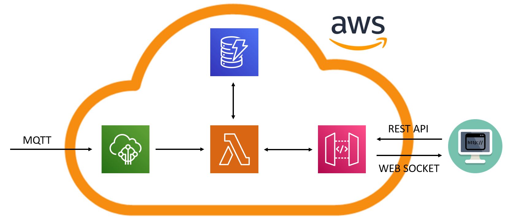
CloudThe image above shows the architecture of the cloud part of the project. The cloud components work as follow:
- AWS IoT-Core: It acts as a MQTT broker receiving the data collected by the board on topic "wl_sensors". Through the execution of a specific rule that sends the incoming data with topic "wl_sensors" to the lambda function "wl-write-lambda".
- AWS DynamoDB: It is the database utility used to store the data collected by the sensors. All the incoming data with topic "wl_sensors" are sent by the IoT-Core to the lambda function wl-write-lambda that computes the new id, the timestamp and store the data in the DynamoDB table "wlTable". The table "wlTable" is a table with 3 columns: id, timestamp and sensorsData. The id is the key of the elements while the column sensorsData contains the data collected by the sensors.
- AWS API Gateway: Is an AWS utility that allows us to create and deploy a REST API to access data. When a GET request is received, the API Gateway invokes the lambda function "wl-api-function" that retrieves the 15 most recent elements stored in "wlTable" and sends it back as response.
- AWS Lambda Functions: AWS Lambda allows us to write some functions to manage the data in different ways. In this case we have two lambda functions:
- wl-write-lambda: This function receives the incoming data with topic "wl_sensor" that are of the form {"water":int, "movement":int, "leak":int}. The function computes the id to assign to the new data, computes the timestamp corresponding to the arrival time of the data, reads the data and stores them in a dynammDB table called "wlTable".
- wl-api-function: This function is connected to the API Gateway and in particular it returns the 15 most recent entries of the DynamoDB table "wl_table" where the elements are sorted by id. (Highest id = Most recent)
The front-end is a web-page that sends a GET request to the aws API gateway in order to obtain the most recent data stored on the cloud.
Those data are then presented in a table and used to plot some charts:
- A global chart where there are three lines representing the data of water, movement and leak.
- Three more chart where the single lines representing water movement and leak are represented.
For further information about the system you can visit the project github repository:
https://github.com/FrancescoCrino/water-leakage-detection-system
The following video shows how to set-up the virtual network environment, how to start the system and also a practical test of my prototype:


Comments
Please log in or sign up to comment.