UPDATE:
1. I changed the Master Control button to use Virtual Pin7. This way when the Timer Starts/Stops the pump, the Master Power button reflects the state correctly.
2. I changed the way the Power saving mode work in order to circumnavigate the use of delay() that was blocking the Current sensor readings. This was done by adding another scheduler to set Power Save times and utilising and IF statement to determine which timer should be activated.
A project that address two simple needs:
1.) Remote control of pumps in agricultural areas - Boron
2.) Energy saving and convenient way to control swimming pool pumps - Photon
PLEASE BE CAREFUL - HIGH VOLTAGEThe scope was to create a device with as few as possible external components such as external PSU and CS. Hence the use of the AC/DC converter to be able to power the device directly from the actual current being monitored/controlled.
Goal:Aside from obvious convenience, the hope is that if users can see in real time the amount of power they are consuming running equipment like swimming pool pumps, they might optimise the run times of these equipment. The holiday mode implementation should also greatly reduce the power consumption during times that the pool is not in use.
First Things First:The purpose of this build was to assist people in easily control High Voltage devices from a mobile device. The device will measure the power consumption, control a load connected to it as well as monitor two external sensors. For the purposes of this Project Share, we will look at the Pool Pump control switch.
PCB Design:Disclaimer: Even though thoroughly tested, I am by no means and expert when it comes to designing PCB’s so please be careful when following these instructions.
There are a some factors to keep in mind when working with higher Voltages and Current on PCB’s. One of the key things is to make sure the traces on the PCB can support the current that will be drawn by the load connected to it. I have found this PCB trace width calculator to be very helpful:
PCB Trace width calculator
As you can see, there is a clear distinction between the 240V traces and the normal traces. I also tried the keep the 240V traces away from the normal traces as far as I could by placing them on the bottom layer of the PCB. Due to the self imposed size constraint, it was not always possible though.
In addition to this, I opted for 2oz copper weight on the traces allowing for a 10-15 degree temperature rise above ambient when at full load.
You can find my Eagle files here:
EAGLE Board File
EAGLE Schematic
The Tough Part:(Work in progress)
C++ … my Achilles heel :-)
The code is attached below. I am sure you will be able to write much neater and more efficient code. If not, this works. I am working to improve the code and will post the edit as soon as I am done.
The Dashboard:As this is more of a consumer product, I opted to go with BLYNK. I think there is more value in being able to control these devices from a mobile device rather a web based dashboard. I am a complete newbie to BLYNK so unfortunately cannot be of much assistance there. If you need help with creating additional layouts, best to approach the forum…
I used the free version as this I am still in prototype stage.
On this APP I have the following:
- Manual ON/OFF Switch
- Simple Scheduler/Timer for both Normal and Power saving modes
- Holiday Mode button
- Push Notifications
- Electricity Unit price selector
- Estimated spent (per hour) display
- kWh display
- Current drawn display
- Pool Temperature display
The pump can be switched on/off at any time using the manual switch. In addition to this, there is a simple scheduler that can be used to set daily run times. BLYNK also offers a more comprehensive Scheduler that will allow you to set days of the week as well, but I have not been able to make it work as it requires more complex coding.
The Holiday Mode button will activate static power saving mode, effectively reducing the runtime to the to the hard coded minutes per day.
A push notification is sent to the mobile device if the switch has been offline for (in my case) more than 5 minutes.
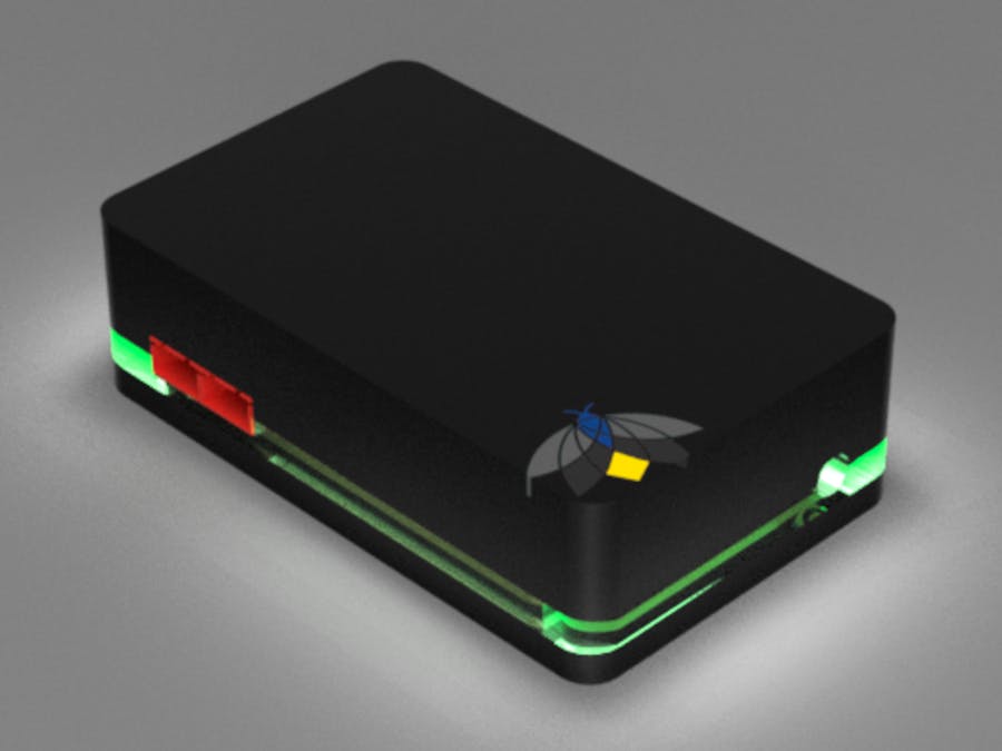
The device make use of simple RGB indicator led. RED means device is online and waiting for run time. BLUE is when connected load is running in normal mode. GREEN is indicating that the load is running in Holiday (energy saving) Mode.
Future Scope:I am planning to add couple more features i.e. preventative maintenance indicator, slider to dynamically set Holiday Mode run time and wireless temperature sensor.
I hope you enjoyed the project. Stay curious, Keep innovating!


Comments
Please log in or sign up to comment.