

Hardware components | ||||||
| × | 1 | ||||
 |
| × | 1 | |||
| × | 1 | ||||
| × | 1 | ||||
 |
| × | 1 | |||
 |
| × | 1 | |||
 |
| × | 1 | |||
| × | 1 | ||||
Software apps and online services | ||||||
| ||||||
Hand tools and fabrication machines | ||||||
 |
| |||||
 |
| |||||
FLAMEX (FLame Alert Monitoring and Extinguishing System) is an IoT project designed to detect fires and extinguish them automatically. The system uses an ESP32 Heltec LoRa32 V2 board, Riot OS, and AWS IoT Core, DynamoDB, MQTT, and LoRa protocol to communicate and store data.
The problem I aim to address is the detection of fire and gas leaks in a building or residential environment. These incidents pose serious risks to life and property and require timely detection and response.
IoT technology enables us to create a connected fire alarm system that enhances traditional fire detection capabilities.
Application Scenario: the goal is to develop a smart fire alarm system for residential buildings. The system will continuously monitor the environment for fire and gas hazards, allowing for early detection and rapid response. By integrating IoT capabilities, the system can provide notifications, automate emergency protocols, and facilitate remote monitoring and control.
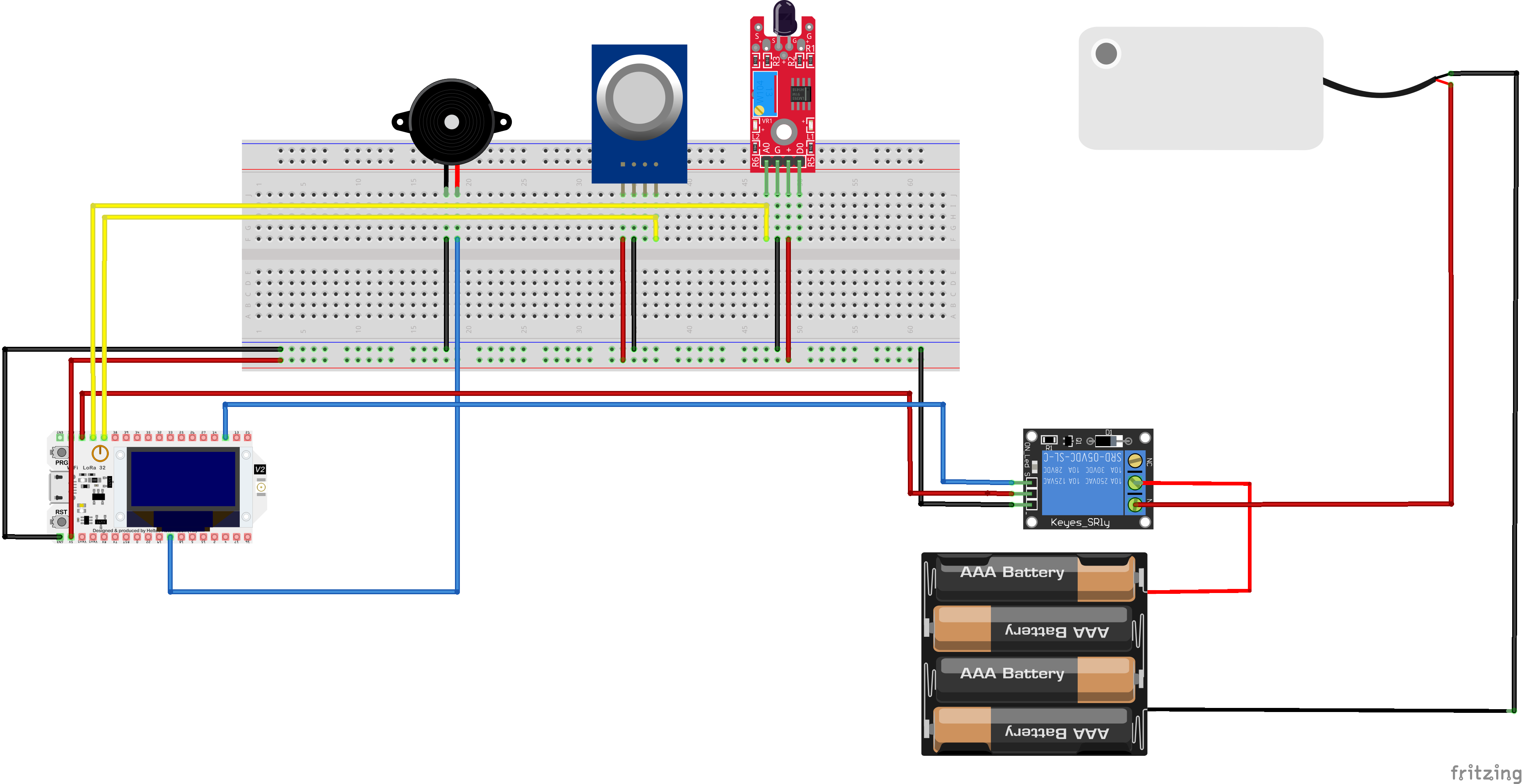
ArchitectureThe circuit is the following:
Let's see the hardware components.
ComponentsBoard
ESP32 Heltec LoRa32 v2
The Heltec LoRa32 v2 is a development board with 8 MB Flash that uses the EPS32 chip directly. It integrates:
- a SemTech SX1276 or SX1278 for LoRaWAN communication and
- a SSD1306 0.96-inch 128x64 OLED display connected via I2C.
Sensors
KY-026 Flame Sensor Module
The KY-026 Flame Sensor module detects infrared light emitted by fire.
This module consist of a 5mm infra-red receiver LED, a LM393 dual differential comparator, a 3296W trimmer potentiometer, 6 resistors, 2 indicator LEDs and 4 male header pins. The board features an analog and a digital output.
- Operating Voltage 3.3V ~ 5.5V
- Infrared Wavelength Detection 760nm ~ 1100nm
- Sensor Detection Angle 60°
- Board Dimensions 1.5cm x 3.6cm [0.6in x 1.4in]
MQ-2 Gas Sensor Module
The MQ-2 gas sensor is used to detect or monitor the concentration and/or presence of combustible gases in the air. It detects LPG, Smoke, Alcohol, Propane, Hydrogen, Methane and Carbon Monoxide concentrations.
- Operating voltage 5V
- Load resistance 20 KΩ
- Heater resistance 33Ω ± 5%
- Heating consumption <800mw
- Sensing Resistance 10 KΩ – 60 KΩ
- Concentration Range 200 – 10000ppm
Actuators
Active Buzzer
This buzzer is an active buzzer, which basically means that it will buzz at a predefined frequency (2300 ±300 Hz) on its own even when you just apply steady DC power.
- Operating Voltage 3.5V ~ 5.5V
- Maximum Current 30mA / 5VD
- Minimum Sound Output 85dB @ 10cm
- Resonant Frequency 2500 ±300 Hz
- Operating Temperature -20°C to 45°C
Relay
Relay is an electromechanical device that uses an electric current to open or close the contacts of a switch. Thanks a single channel relay shield, it is possible to turn on and off lamps, fans, solenoids, and other small appliances that run on up to 250VAC or DC power.
- Supply voltage – 3.75V to 6V
- Quiescent current: 2mA
- Current when the relay is active: ~70mA
- Relay maximum contact voltage – 250VAC or 30VDC
- Relay maximum current – 10A
Water pump
This is a low cost, small size Submersible Pump Motor which can be operated from a 2.5 ~ 6V power supply. It can take up to 120 liters per hour with very low current consumption of 220mA.
- Operating Current : 130 ~ 220mA
- Operating Voltage : 2.5 ~ 6V
- Flow Rate : 80 ~ 120 L/H
- Maximum Lift : 40 ~ 110 mm
- Driving Mode : DC, Magnetic Driving
- Continuous Working Life : 500 hours
- Material : Engineering Plastic
- Outlet Outside Diameter : 7.5 mm
- Outlet Inside Diameter : 5 mm
- IoT Devices with RIOT OS: The pet tracking system utilizes IoT devices equipped with the RIOT OS (Real-Time Operating System). These devices, such as the ESP32 v2 Heltec LoRa board, incorporate the necessary hardware components, to track and monitor pets effectively. RIOT OS provides a lightweight and efficient operating system tailored for resource-constrained IoT devices, ensuring optimal performance and low power consumption.
- The Things Network (TTN): The Things Network plays a crucial role in the pet tracking system's network architecture. TTN serves as the LoRaWAN infrastructure provider, enabling secure and reliable communication between the IoT devices and the cloud service. It facilitates the seamless transmission of location data from the IoT devices to the cloud service, ensuring efficient data flow and connectivity.
- Python client for interfacing with TTN: To facilitate the configuration of geofence boundaries, a Python TTN client is employed. This client interacts with TTN to provide the precise coordinates of the geofence to the IoT devices. By leveraging this client, the system establishes an effective means of defining and updating the designated area in which pets should remain.
- Amazon Web Services: The pet tracking system leverages several components within the AWS ecosystem to enable data storage, processing, and web interface access. The components utilized include:
- AWS IoT Core: It serves as the central hub for communication between the pet tracking devices and the cloud service. AWS IoT Core enables secure and reliable data exchange and facilitates seamless integration with other AWS services.
- DynamoDB: This NoSQL database service is employed for storing the pet's location data. DynamoDB offers scalability, high performance, and low latency access, ensuring efficient storage and retrieval of location data.
- Lambda Functions: AWS Lambda functions are utilized to perform various operations on the pet's location data, including encryption, decryption, and data processing. These serverless functions enable real-time data manipulation and facilitate seamless integration with other AWS services.
- Amplify: AWS Amplify simplifies the development process by providing a set of tools and services for building scalable and secure web applications. It enables the creation of a user-friendly web interface for pet owners to access real-time location data and receive alerts.
- API Gateway: AWS API Gateway acts as the entry point for the web interface, providing a secure and scalable API endpoint. It enables seamless communication between the web interface and the backend services, ensuring a smooth user experience.
The user interface is accessible through this link
The code /*
* Copyright (C) 2023 Francesco Fortunato
*
* This file is subject to the terms and conditions of the MIT License.
* See the file LICENSE in the top level directory for more details.
*/
/**
* @ingroup examples
* @{
*
* @file
* @brief Example demonstrating the use of LoRaWAN with RIOT
*
* @authors Francesco Fortunato <francesco.fortunato1999@gmail.com>
*
* @}
*/
#include "stdio.h"
#include "stdlib.h"
#include "time.h"
#include "thread.h"
#include "periph/adc.h"
#include "periph/gpio.h"
#include "periph/i2c.h"
#include "analog_util.h"
#define IR_FLAME_PIN ADC_LINE(0)
#define GAS_PIN ADC_LINE(2)
#define ADC_RES ADC_RES_12BIT
#define BUZZER_PIN GPIO_PIN(0, 23)
#define RELAY_PIN GPIO_PIN(0, 12)
#define DELAY (60 * US_PER_SEC)
#define FLAME_THRESHOLD 70 // Set threshold for flame value here
#include "periph/pm.h"
#if IS_USED(MODULE_PERIPH_RTC)
#include "periph/rtc.h"
#else
#include "timex.h"
#include "ztimer.h"
#endif
#include "xtimer.h"
#include "net/loramac.h"
#include "semtech_loramac.h"
/* Low-power mode level */
#define PM_LOCK_LEVEL (1)
#define MAX_JOIN_RETRIES 3
extern semtech_loramac_t loramac;
#if !IS_USED(MODULE_PERIPH_RTC)
static ztimer_t timer;
#endif
#ifdef USE_OTAA
static uint8_t deveui[LORAMAC_DEVEUI_LEN];
static uint8_t appeui[LORAMAC_APPEUI_LEN];
static uint8_t appkey[LORAMAC_APPKEY_LEN];
#endif
uint8_t *msg_to_be_sent;
char* msg_received = NULL;
char stack1[THREAD_STACKSIZE_MAIN];
char stack2[THREAD_STACKSIZE_MAIN];
kernel_pid_t thread_pid_buzzer;
kernel_pid_t thread_pid_pump;
int sample_fire = 0;
int sample_gas = 0;
int flame = 0;
int gas_value = 0;
float voltage_flame = 0;
float voltage_gas = 0;
bool fire;
bool gas;
bool buzz;
bool pump;
bool joinLoRaNetwork(void) {
int joinRetries = 0;
while (joinRetries < MAX_JOIN_RETRIES) {
/* Start the Over-The-Air Activation (OTAA) procedure to retrieve the
* generated device address and to get the network and application session
* keys.
*/
printf("Starting join procedure (attempt %d)\n", joinRetries + 1);
if (semtech_loramac_join(&loramac, LORAMAC_JOIN_OTAA) == SEMTECH_LORAMAC_JOIN_SUCCEEDED) {
printf("Join procedure succeeded\n");
return true; // Join successful, return true
} else {
printf("Join procedure failed\n");
joinRetries++;
}
}
printf("Exceeded maximum join retries\n");
return false; // Join failed after maximum retries, return false
}
void *buzzer_thread(void *arg)
{
(void) arg;
while(1) {
if(buzz) {
printf("BUZZ ON\n");
gpio_set(BUZZER_PIN);
xtimer_usleep(1000000); // Wait for 1s
gpio_clear(BUZZER_PIN);
xtimer_usleep(400000); // Wait for 400ms
} else {
thread_sleep();
}
}
return NULL;
}
void *pump_thread(void *arg)
{
(void) arg;
while(1) {
if (pump) {
printf("POMPA PARTITA\n");
gpio_clear(RELAY_PIN);
xtimer_sleep(5);
} else {
printf("POMPA FERMATA\n");
gpio_set(RELAY_PIN);
thread_sleep();
}
}
return NULL;
}
int main(void)
{
// Seed the random number generator
printf("FLAMEX: a LoRaWAN Class A low-power application\n");
printf("===============================================\n");
/*
* Enable deep sleep power mode (e.g. STOP mode on STM32) which
* in general provides RAM retention after wake-up.
*/
#if IS_USED(MODULE_PM_LAYERED)
for (unsigned i = 1; i < PM_NUM_MODES - 1; ++i) {
pm_unblock(i);
}
#endif
#ifdef USE_OTAA /* OTAA activation mode */
/* Convert identifiers and keys strings to byte arrays */
fmt_hex_bytes(deveui, CONFIG_LORAMAC_DEV_EUI_DEFAULT);
fmt_hex_bytes(appeui, CONFIG_LORAMAC_APP_EUI_DEFAULT);
fmt_hex_bytes(appkey, CONFIG_LORAMAC_APP_KEY_DEFAULT);
semtech_loramac_set_deveui(&loramac, deveui);
semtech_loramac_set_appeui(&loramac, appeui);
semtech_loramac_set_appkey(&loramac, appkey);
/* Use a fast datarate, e.g. BW125/SF7 in EU868 */
semtech_loramac_set_dr(&loramac, LORAMAC_DR_5);
/* Join the network if not already joined */
if (!semtech_loramac_is_mac_joined(&loramac)) {
/* Start the Over-The-Air Activation (OTAA) procedure to retrieve the
* generated device address and to get the network and application session
* keys.
*/
if (!joinLoRaNetwork()) {
printf("Failed to join the network\n");
return 1;
}
#ifdef MODULE_PERIPH_EEPROM
/* Save current MAC state to EEPROM */
semtech_loramac_save_config(&loramac);
#endif
}
#endif
printf("You are running RIOT on a(n) %s board.\n", RIOT_BOARD);
printf("This board features a(n) %s MCU.\n", RIOT_MCU);
if(adc_init(IR_FLAME_PIN) < 0){
printf("Failed to initialize ADC for flame sensor\n");
return 1;
} else {
printf("Flame sensor ADC OK\n");
}
if(adc_init(GAS_PIN) < 0){
printf("Failed to initialize ADC for gas sensor\n");
return 1;
} else {
printf("Gas sensor ADC OK\n");
}
// Initialize the buzzer pin as output
if(gpio_init(BUZZER_PIN, GPIO_OUT) < 0) {
printf("Failed to initialize buzzer pin\n");
return 1;
} else {
printf("Buzzer pin OK\n");
}
// Initialize the relay pin as output
if(gpio_init(RELAY_PIN, GPIO_OUT) < 0) {
printf("Failed to initialize relay pin\n");
return 1;
} else {
gpio_set(RELAY_PIN);
printf("Relay pin OK\n");
}
thread_pid_buzzer = thread_create(stack1, sizeof(stack1),
THREAD_PRIORITY_MAIN + 2,
THREAD_CREATE_SLEEPING,
buzzer_thread,
NULL, "buzzer_thread");
thread_pid_pump = thread_create(stack2, sizeof(stack2),
THREAD_PRIORITY_MAIN + 1,
THREAD_CREATE_SLEEPING,
pump_thread,
NULL, "pump_thread");
//Timer
xtimer_ticks32_t last = xtimer_now();
fire = false;
gas = false;
pump = false;
buzz = false;
while (1) {
sample_fire = adc_sample(IR_FLAME_PIN, ADC_RES);
voltage_flame = adc_util_map(sample_fire, ADC_RES, 4095, 0);
flame = adc_util_map(sample_fire, ADC_RES, 100, 1);
sample_gas = adc_sample(GAS_PIN, ADC_RES);
voltage_gas = adc_util_map(sample_gas, ADC_RES, 4095, 0);
gas_value = adc_util_map(sample_gas, ADC_RES, 1, 100);
fire = (flame > FLAME_THRESHOLD) ? true : false;
gas = (gas_value > 40) ? true : false;
if(gas || fire) {
buzz = true;
thread_wakeup(thread_pid_buzzer);
if(gas){
printf("GAS DETECTED\n");
}
else{
printf("NO GAS DETECTED\n");
}
if(fire){
printf("FIRE DETECTED\n");
pump = true;
thread_wakeup(thread_pid_pump);
}
else{
printf("NO FIRE DETECTED\n");
pump = false;
}
}
else{
buzz = false;
pump = false;
}
printf("Voltage_fire: %.2f mV\tFlame: %d\n", voltage_flame, flame);
printf("Voltage_gas: %.2f mV\tGAS: %d\n", voltage_gas, gas_value);
char json[200];
if (!pump){
sprintf(json, "{\"id\": \"%d\", \"voltage\": \"%.2f\", \"flame\": \"%d\", \"gas\": \"%.2d\", \"pump\": \"NON_ACTIVE\"}",
1, voltage_flame, flame, gas_value);
}
else{
sprintf(json, "{\"id\": \"%d\", \"voltage\": \"%.2f\", \"flame\": \"%d\", \"gas\": \"%.2d\", \"pump\": \"ACTIVE\"}",
1, voltage_flame, flame, gas_value);
}
msg_to_be_sent = (uint8_t *)json;
printf("Sending: %s\n", msg_to_be_sent);
uint8_t ret = semtech_loramac_send(&loramac, (uint8_t*)msg_to_be_sent, strlen(json));
if (ret != SEMTECH_LORAMAC_TX_DONE)
{
printf("Cannot send message '%s', ret code: %d\n", msg_to_be_sent, ret);
free(msg_to_be_sent);
}
xtimer_periodic_wakeup(&last, DELAY);
}
}- Initialization and LoRaWAN Setup:
The code starts by including essential header files and defining necessary constants. It sets the stage for LoRaWAN integration, ensuring smooth execution. The LoRaWAN stack is initialized, and parameters for Over-The-Air Activation (OTAA) mode are configured, including device identifiers and keys. These details are crucial for successful network joining.
- Multithreading for Concurrent Execution:
To handle concurrent tasks efficiently, the code introduces two distinct threads: buzzer_thread and pump_thread. These threads operate independently while sharing resources. The buzzer_thread manages the buzzer
functionality, while the pump_thread controls the pump's behavior. This multithreaded approach enhances responsiveness and enables parallel execution of critical operations.
- Sensor Initialization and Data Acquisition:
The main function takes charge, initializing various components necessary for the application. It configures the Analog-to-Digital Converter (ADC) to interface with flame and gas sensors. Additionally, GPIO pins are set up for the buzzer and relay. These preparations ensure seamless data acquisition and control over the connected peripherals.
- Real-time Monitoring and Decision Making:
The main loop of the code acts as the central hub for real-time monitoring. It continuously samples values from the flame and gas sensors, converting them into corresponding voltage values. By applying predefined threshold values, it determines the presence of fire or gas. These decisions influence the variables buzz and pump, triggering subsequent actions.
- Buzzer and Pump Control:
Upon gas detection, the buzz variable is set to activate the buzzer, alerting users to potential dangers. The associated buzzer_thread is awakened, allowing it to control the buzzer's behavior. Similarly, in the event of fire detection, the pump variable is adjusted, signaling the need to activate the pump. The pump_thread takes charge, controlling the relay to initiate or halt the pump's operation. This intelligent decision-making process enhances safety measures and facilitates prompt responses.
- LoRaWAN Communication:
To transmit the sensor data and pump status, the code constructs a JSON message encapsulating the relevant information. This message is intended for transmission over the LoRaWAN network. Utilizing the capabilities of the LoRaWAN stack in RIOT, the code sends the message to the network server. Error handling is included to address potential transmission failures, ensuring data reliability and integrity.
EvaluationThe end-to-end latency is calculated from the point the data are collected from the sensor up to the point they are integrated in the dashboard:
- Sensor to Gateway:
The latency from the sensor to the LoRaWAN gateway range from 1 second to 2 seconds, depending on factors such as signal strength, interference, and the distance between the sensor and gateway.
- Gateway to Cloud:
This latency is whithin the range of 1 second to 3 seconds. However, in optimized setups with high-speed internet connections and low network congestion, latencies as low as tens of milliseconds can be achieved.
- Cloud Processing and Integration:
Latency in this stage is varying widely, few seconds to 5, 6 seconds.
The volume of data transmitted over the network: in the provided code, since the sensor data is encapsulated in a JSON message before transmission, the size of the JSON message depends on the length of the transmitted data fields is ca. 200 bytes. The number of data transmissions depends on the frequency at which the main loop is executed. In the code, the main loop uses a delay of 10 seconds, so the number of data transmissions per hour is:
Number of data transmissions per hour = 3600 seconds / 10 seconds = 360 transmissions
To calculate the volume of data transmitted over the network per hour, we multiply the size of each transmission by the number of transmissions:
Volume of data transmitted over the network per hour = 200 bytes * 360 transmissions = 72, 000 bytes (or 72 kilobytes)
Of course the code is only an example and the datarate is only for demonstration purposes: data should be sent only if gas or fire is detected.


Comments