


Hardware components | ||||||
 |
| × | 1 | |||
| × | 1 | ||||
| × | 1 | ||||
| × | 1 | ||||
| × | 4 | ||||
| × | 1 | ||||
| × | 1 | ||||
Software apps and online services | ||||||
| ||||||
| ||||||
Hand tools and fabrication machines | ||||||
| ||||||
Hello,
Let us get started!
Attach your MotorCape to the BBBW, firstly.
Next, we need to plug everything in!
So, the two wires that will go to the battery, do not plug them in to the battery just yet, need to go in the center markings that show positive and negative on the MotorCape.
Fasten them w/ your screw driver and the screws in the connector housing!
Tug on them slightly to make sure they are lodged good and firm.
Next...
Take your solenoid lock/latch and attach the wires from it to the MotorCape Motor1 connectors. Either way is fine, i.e. as they are only on Motor1 and only Motor1.
...
Again, tug slightly to make sure they are attached well enough so that they do not come loose.
Now and this only pertains to people that have come to the point of already attaching their Cape, setting up the distro from beagleboard.org/latest-images or your own image or whatever.
Attach a Micro USB to USB 2.0 cable to the BBBW and the development computer.
Again, the Cape should already be attached and attached correctly.
...
So, P9 on the Cape goes to P9 on the BBBW, respectively.
Trust me, I have, in the heat of battle, made simpler mistakes and got it to take the joy out of making automation work for me...
Okay, enough downfalls here.
Now, we need to, if we have attached the Cape to the BBBW and attached the USB Cable to the BBBW and dev. desktop, add the USB to barrel jack cable to the power bank and barrel jack on the BBBW.
Now, if the wires are plugged in like discussed earlier, be careful if you are using 1.5v or over (preferably 12vdc Lead Acid for testing for the Cape to function correctly) that voltage as DC (direct current) can irritate or hurt you over and over and over. Heads Up!
Okay...so!
We have everything plugged in but the 12v DC Lead acid battery w/ the quick disconnects. Use a crimp tool before plugging in the 12vdc battery to the Cape.
Crimp your disconnects to the wires attached to the positive and negative terminals on the Cape.
Once all the above is completed...plug in the Ground/Negative cable first to the Lead Acid battery and then plug in the Power/Positive side next.
Now, w/ networking available due to the WiFi signal on the BBBW and the Micro USB to USB 2.0, we can finally throw together some simple source to handle this solenoid latch!
...
I will show a couple photos soon to have a review of the above examples of quick orders on how to advance in the latch_solenoid field.
See the red signifying positive and the black signifying GND? Nice! Remember!
...
Power Bank w/ USB 2.0 to barrel jack connection!
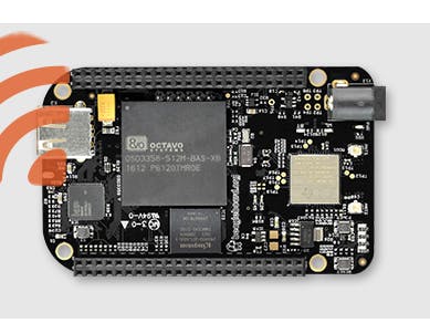
BBBW w/ some other hardware and the MotorCape!
A simple solenoid lock/latch for automation!
...
Okay. So, w/ some simple and cautious ideas, take everything that is put together and run some source!
import Adafruit_BBIO.GPIO as GPIO
import Adafruit_BBIO.PWM as PWM
import time

class Motor:
    def __init__(self, dir_pin, pwm_pin, pwm_freq):
        self.dir_pin = dir_pin
        self.pwm_pin = pwm_pin
        self.value = 0

        PWM.start(pwm_pin, 0, pwm_freq)
        GPIO.setup(dir_pin, GPIO.OUT)

    def set(self, value):
        assert -100 <= value <= 100
        if (value < 0) != (self.value < 0):
            # changing direction
            PWM.set_duty_cycle(self.pwm_pin, 0)
            GPIO.output(self.dir_pin, value < 0)
        PWM.set_duty_cycle(self.pwm_pin, abs(value))
        self.value = value

motor1 = Motor(dir_pin="P8_18", pwm_pin="P9_16", pwm_freq=2000)

def updates():
    state = int(input("Please enter a 0 or 1 for action: "))
    for state in range(0, 10):
        if state == 1:
            motor1.set(100) # this will give the solenoid 100 % power to retract!
            time.sleep(2)
            motor1.set(0) # this will make the solenoid lock back in place!
            time.sleep(2)

        elif state == 0:
            motor1.set(0)

        else:
            motor1.set(0)

updates()
...
Seth
P.S. I received some help w/ this source from #beagle on Freenode.

Comments
Please log in or sign up to comment.