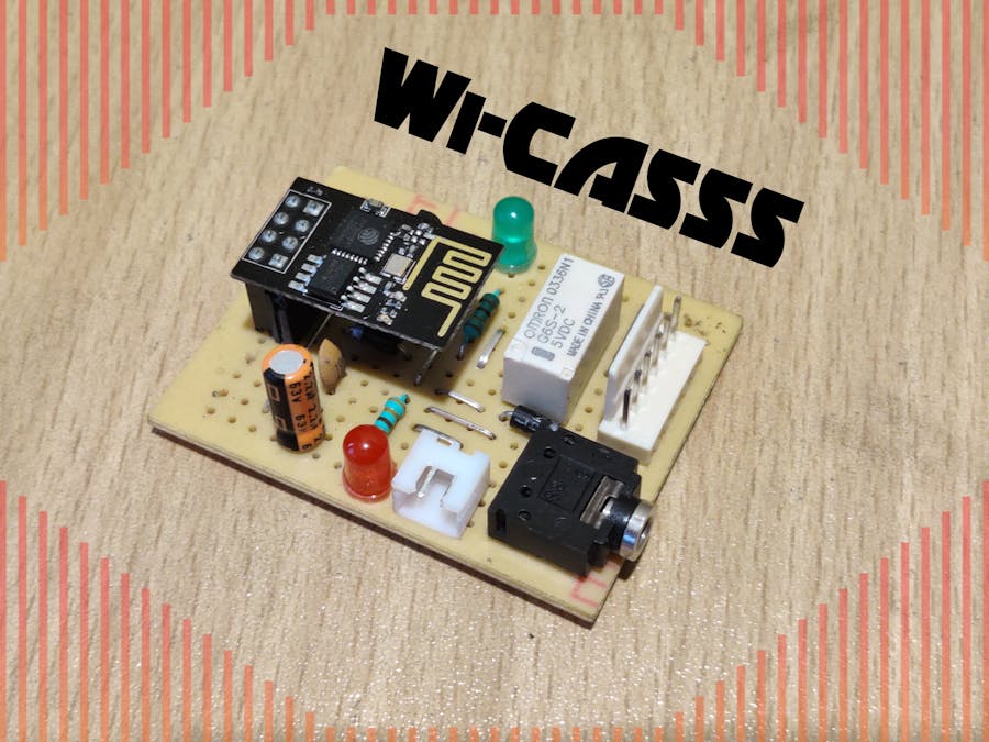
Most of the audio devices used even today, widely adopt the 3.5 mm or the differential audio jacks for the transmitting the audio signals via a cable. Though this concept is changing in mobile devices by shifting towards wireless audio, but most of the bulkier audio devices such as the TV or a bookshelf speakers, still use the wired medium for transmitting audio.
These audio jacks are usually placed at the rear end of the devices which are difficult to reach once they're set-up on a desk or a stand unit. So whenever the user wants to connect a new Audio Device like an iPod or a new set of speakers, the user always has to unplug and re-insert the respective cable for the device. This makes it very inconvenient for the user, especially when the cables have to be frequently swapped in and out.
So in this project I have designed a remote WiFi Controlled Audio Source Selector Switch (Wi-CASSS) which enables the user switch between two connected input/output audio devices over internet. Hence this removes the difficulty of swapping in the audio cables every time one connects a new device.
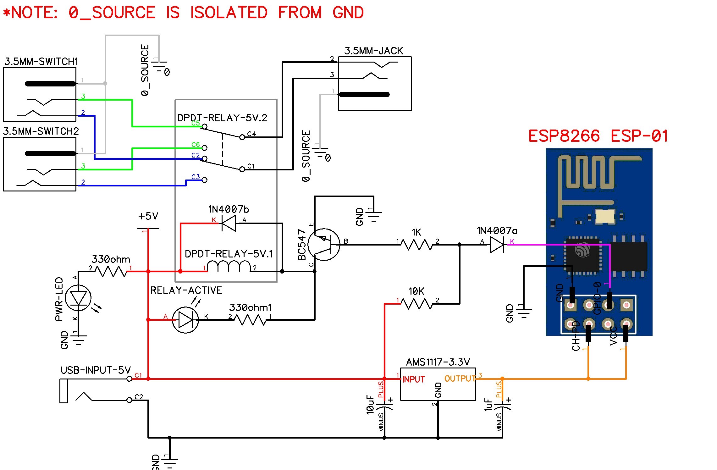
- The circuit consists of a Double Pole Double Throw(DPDT) Relay which switches the Left & Right Channel of the audio signals into two separate channels. Since relays are just an electromechanical switch, they don't distort the audio signals and most importantly, they are bi-directional. So audio signals can be given from any direction.
- For convenience, the whole circuit is powered by 5V which is easily accessible via a USB port.
- The DPDT Relay used in this project is OMRON G6S-2 (5V) relay which according to its data sheet, is best suitable for Signal Switching.
- For the Wi-Fi module, the requirement was to only switch a single relay which means only one GPIO was necessary. So I went with the 8-Pin ESP8266 ESP-01 module.
- Now this Relay is switched ON/OFF (using a transistor switching circuit) depending upon the signal received by one of the GPIOs of the ESP8266 ESP-01.
In order to avoid distortions in the audio signals, the ground pin of the audio devices connected are ISOLATED from the ground pin of the 5V USB power source.Components Needed:
- 1x ESP8266 ESP-01 Wi-Fi Module
- 1x OMRON G6S-2 (5V) DPDT Relay
- 2x 3.5mm Male Audio Jacks
- 1x 3.5mm PCB Mountable Female Audio Jack
- DC Jack (2-Pin) For USB Power (5V)
- 2x 1N4007 Diode
- 2x LEDs (Different Color. One for Power Indicator & the other to indicate Relay State)
- 2x 330ohm, 1x 1Kohm, 1x 10Kohm - 1/4 watt resistors
- 1x BC547 NPN Transistor
- Small Size Perforated Circuit Board
- 1x 1uf, 1x 10uf Capacitors
- 6pin Polarized Header Pin Connector Set.
- Female Header Pin for Mounting ESP8266
- 1x AMS1117 3.3V Fixed Voltage Regulator
- Check out the Circuit Diagram and place the components on the circuit board in such a way which would require the least amount of soldering traces. After finalizing, start soldering.
- Now cut down 2x - 4pin female headers for the ESP8266. Verify the connections for the ESP8266 and mark its corresponding pins with a colored marker for convenience like on the image and start soldering. NOTE: ESP8266 works only on 3.3V. Hence it should only be connected to the 3.3V regulator pin.
- At last mount the 3.3V AMS1117 Fixed Voltage regulator and complete the soldering.
- Connect the 6 pin polarized header pin to the 2x 3.5mm male audio jacks as shown below.
The Arduino IDE installed in your PC must include board manager data for ESP8266. After that use a Serial to USB converter for programming your ESP-01. In my case I used an Arduino NANO to program the ESP-01.
- In your mobile, install the Blynk App from the Play Store or App Store and create an account.
- After creating an account, click on create a new project with board selected as ESP8266. Then you will get an authorizing code in your email. Keep the code copied in your clip board.
- Now create a button as shown in the image below and select the pin number of GPIO.
Now install the Blynk Library on Arduino IDE and take the example code of Standalone WiFi or take the attached code in this project. In this code, modify the Network Name SSID to your corresponding home network name and add the password on the next line. On the "auth token" space, paste the authorization code which you received from the email for the project and finally click on RUN.Testing:
- I connected an iPod and an iPhone as two source inputs to the Wi-CASSS. For the output I attached a 5-Watt 2.0 Channel Speaker.
- The iPhone itself was used to operate the Blynk application.
Then Audio was played simultaneously in both devices and the speaker provided output only for one of the device depending upon the selection made on the Blynk application.
LEFTImage (1)- The audio source is selected from the iPod and hence the relay is inactive and the Green LED is off.
RIGHTImage (2) - The source is now switched from iPod to iPhone in the Blynk App and the speaker is now providing audio output from the iPhone only. So now the Green LED is turned ON and the Relay remains active.Conclusion:
Using WiFi controlled switch provides more range of distance for switching (If internet is connected, the Wi-CASSS can be switched from anywhere around the world) and makes it easier to control via smartphone.
Depending upon the requirement, the user can replace the WiFi module with an IR Remote Control or Bluetooth Module, and mount it over the same Audio Switching Relay Circuit.
THANK YOU!


Comments
Please log in or sign up to comment.