


Hardware components | ||||||
| × | 1 | ||||
| × | 2 | ||||
| × | 1 | ||||
 |
| × | 1 | |||
| × | 1 | ||||
| × | 1 | ||||
 |
| × | 1 | |||
 |
| × | 1 | |||
| × | 1 | ||||
| × | 1 | ||||
| × | 1 | ||||
| × | 1 | ||||
Software apps and online services | ||||||
 |
| |||||
Hand tools and fabrication machines | ||||||
 |
| |||||
 |
| |||||
| ||||||
| ||||||
| ||||||
| ||||||
Here's my first attempt at interactive wall art!
This mechanical coin display shows off two canadian $2 coins (aka toonies). The left toonie is a special Queen Elizabeth Memorial coin and the right toonie is a generic one.
When the knob is turned the coins will be illuminated and will rotate in sync. The rotation mechanism is fully mechanical.
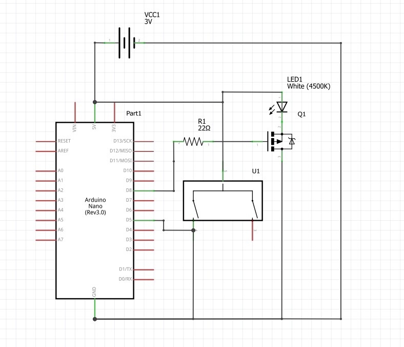
The coin display works on a modified Arduino Nano. The schematic is as follows:
The device is powered with 2xAA batteries (3v). The 5v LDO on the arduino was removed and the 5v pin was used as a 3v input directly to the microcontroller.
As mentioned, the 5V LDO needs to be removed, which is a four-pin IC on the back of the board. Additionally, it is recommended to remove the PWR LED and the 16 pin CH340G IC to preserve battery life. Removing the CH340G will mean the Arduino can not be programmed by normal means.
NOTE: DO NOT REMOVE the CH340G until you have programmed the board and confirmed the code works. After removing this chip you will not be able to program the Arduino over USB.
CodeThe code for this project was written in Arduino. It uses the low-power mode of the microcontroller to sleep after each iteration of the main loop. A pin-change interrupt is used to detect encoder input and wake up the microcontroller.
The main loop runs once when the device is booted up. The lights are faded in, and a timeout counter is incremented every 30 ms. Once the lights are at full brightness they will remain illuminated as long as the timer has not elapsed. If a pin-change interrupt occurs the timer is reset to zero which keeps the lights on.
After the timeout elapses with no user input, the lights are faded out, the counter is reset to zero and the microcontroller enters sleep mode indefinitely.
Any occurrence of the interrupt will wake the microcontroller and fade in the lights again.
The code requires two libraries that can be installed through the arduino IDE library manager.
Required Libraries:
I started off this build with a log off-cut (aka "cookie") that had an interesting shape and pattern.
I had this piece of wood for a while before I decided to use it for the coin display project. This gave the wood lots of time (1+ year) to finish drying out. I noticed the wood cookie looked a lot like a Canadian $2 coin, which made it perfect for this project.
The first step was filling the large crack in the piece with epoxy. I put the wood piece face down and sealed the edges off with painters tape. I mixed the epoxy with metallic pigment according to the pigment instructions and started filling the crack. Unfortunately the painters tape did effectively seal the edges and I had several large leaks. I fixed this by quickly sealing the edges with hot glue and re-filling the crack with extra epoxy.
After the epoxy had cured, I used a belt sander to sand all the epoxy that had leaked on the front and back. I also used a chisel to knock off the extra epoxy protruding past the bark.
After sanding all the epoxy off the front of the piece, I drew a set of axis on the front and took a photo of the piece from directly above. I imported the image into Inkscape, a free vector graphics software. I scaled up the image to make sure it was actual size using some one inch markers I had made on both of the axis.
In Inkscape I created a design to laser-etch onto the piece. I created a separate engraving file with alignment dots that corresponded to points I drew on the piece. These alignment dots would be used to align the piece in the laser cutter bed so the text lined up perfectly with the piece.
To laser engrave the piece, first I engraved the alignment dots several times, adjusting the angle of the piece in between each attempt. Once the dots lined up, I engraved the text.
Next I started designing the mechanics for rotating the coin. I based the mechanism on lego gears since they were cheap and easy to use. I created a prototype mechanism with two gears on either side of a smaller gear which would be turned by the user. Some 90 degree gears were added to the two larger gears to turn the axis of rotation 90 degrees to the input knob.
I 3D modelled parts to hold the gears and axels. I made sure to add a spot to install an encoder so the microcontroller could quickly detect partial rotations of the axel. I also modelled support parts such as: an axel to encoder coupler, an axel compatible coin holder, and an axel spacer. The coin holder slit needed to be tightened up a bit to properly hold one of the coins. I accomplished this with a heat gun and some tweezers.
I 3D printed each part and tested the fit using a flat piece of plywood I was using for laser engraving testing.
After the mechanics were finalized, I used them to position the coins and the knob on the display.
I drilled small holes where each of these three main parts would be positioned. I made sure to drill completely through the piece so I knew where each part would be on the reverse side.
I roughed out the holes for the coins as well as the area I would need to route out on the back of the piece. I used my router with a top-bearing flush cut bit to slowly take off layers until I reached the depth I needed. Unfortunately I did not flatten the back of the piece first so my routing job was uneven and too thin in one place. I fixed this by mixing wood glue with sawdust and applying it to the area that was too thin.
Then I drilled the holes for the coins. I found this was easiest with a drill press and a hole saw. The hole saw was not deep enough to get through the entire thickness, so I just flipped the piece around and drilled from the other side. The pilot hole was used to make sure both sides lined up.
To get the axel through the bottom of the coin holes I ended up routing a channel out through the bottom of the holes.
Before installing the components I made sure to apply a finish to the front of the piece. I chose a water-based marine varnish with a satin finish.
After the finish was applied it was time to install the components!
I made a backplate out of plywood to add some more space for the coins and to close up the back of the coin holes. I used the drill press and a forstner bit to drill the coin holes partly into the backplate.
I assembled the mechanism and attached it to the wood using some small screws and superglue. After testing that the mechanism worked properly, I superglued all the lego in place so that the mechanism would not come apart. I installed the knob on the front (that I already had from a previous project).
I screwed the backplate to the piece and added some keyhole mounting hardware. Finally, I assembled the electronics and glued them into the back of the piece so they would fit and not interfere with the mechanism.
Finally, I picked out a nice spot on the wall for my new interactive coin display!


_3u05Tpwasz.png?auto=compress%2Cformat&w=40&h=40&fit=fillmax&bg=fff&dpr=2)
Comments
Please log in or sign up to comment.