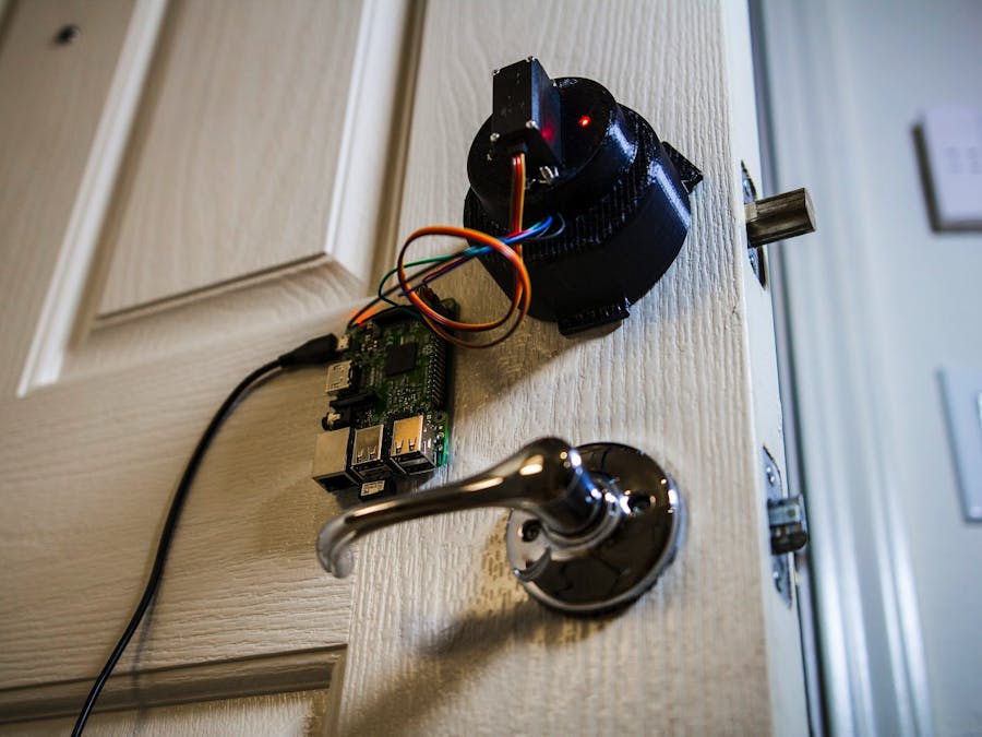
In this project, we show you how to make a smartphone-controlled, internet-connected deadbolt actuator powered by a Raspberry Pi that can be added onto your existing door lock without any modifications to the door. The door lock can be controlled by multiple smartphones, and even notify you whenever someone locks/unlocks the door. All of this is done using a simple, drag-and-drop app builder which makes building your own Internet of Things (IoT) app easier than ever. For an extra impressive door lock, we'll also show you how to add a simple LED light to indicate if the door is locked, and a push-button to operate the lock manually.
Get the 3D printable parts for this project from our Patreon: https://www.patreon.com/posts/smart-doorlock-37732960
How it WorksYou can see the functionality of this mechanism by watching our full build video:
To drive the deadbolt on the door lock, we used a high torque, metal gear servo. Tower Pro makes a cheap one called the MG996R which you can find on eBay for about $5.00. With 8kg/cm of torque at 5v, it should have more than enough power for your particular application.
To hold the servo in place, we created a small 3d printed enclosure. The housing mounts on top of the door lock with some 3M outdoor mounting tape, and a deadbolt adapter piece attaches to the large two sided servo horn that comes with the MG996R. We used some Gorilla glue to make sure the adapter had a strong bond to the servo horn.
All of the 3D printed parts for our project can be found on our website. If you don’t have a 3D printer, you can usually find one at a local library or school. If they do not have a 3D printer, there are also many websites online that can print the files for you. We also created some schematics for wooden MDF parts as an alternative.
The servo body was attached to the door lock housing with four M3 bolts and nuts, we made sure to keep the servo flanges on the inside of the housing so that most of the body was outside of the door lock. Make sure to orient the servo so that its pivot point is in the center of the housing. Some force had to be applied to squeeze the servo wires through.
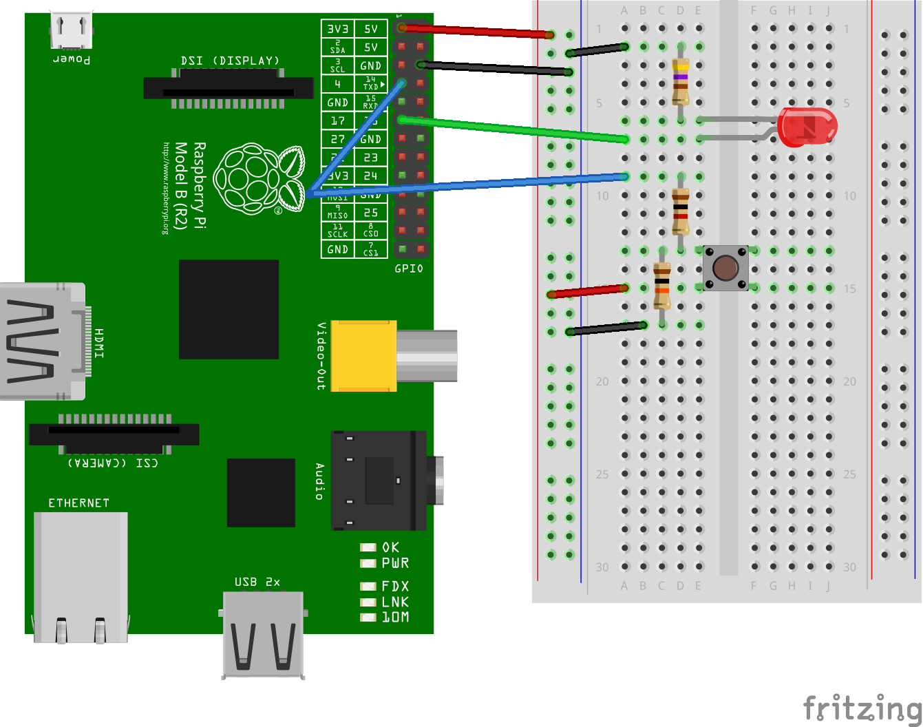
FeaturesA couple extra features were added including an LED light to indicate lock status and a push button to open/close the lock manually. A 470 ohm resistor was wired in series with a red led and 1k/10k ohm resistors were wired in parallel with one of the pins on our switch. We used a few small jumper wires so that they could fit through the small gap in the door lock housing.
We attached the components to the slots in the housing. To hold them in place, we used some glue and let them sit overnight to dry. For extra support, you can also use some electrical tape to back the components.
Raspberry Pi as ControllerA Raspberry Pi was used to control the door lock. We used a Raspberry Pi 3 since it has onboard WiFi capabilities. However, any Raspberry Pi with a WiFi dongle should work with our code. We plugged in the components to their respective pins on the pinout diagram. We used a small screwdriver to switch the brown ground wire and red power wire on the servo connector so that we could attach it directly to the Raspberry Pi.
BlynkWe used an IoT app called Blynk for this project. Blynk easily allows you to connect to a single chip board like the Raspberry Pi through their easy-to-use SDK. After downloading the app from the app store, we created a new project for a Raspberry Pi with “Connection Type” WiFi. I created two components in the interface. The first was a button, connected to virtual pin 0, that controls the state of the servo motor. The second was a push notifications component to be alerted when the door state changes. Finally, you’ll want save the Blynk authentication token by clicking on the gear icon in the main menu, then sending it to your email. This token will be used in the next step.
Next, I connected to my Raspberry Pi. You’ll want to make sure you have node.js installed on your Raspberry Pi. Adafruit has a nice guide on their website. A full set of instructions on how we launched the code can be found on our Github page.
Mounting the Door LockTo mount the door lock housing, we used some strong double-sided 3M outdoor mounting tape (which is great because it leaves no residue). We toggled the servo a few times with the app to make sure it was moving in the right direction. With the tab below the servo facing down, we aligned the door lock connector with the center of the deadbolt and attached it to the door. We also used a couple pieces of mounting tape to attach the Raspberry Pi to the wall next to it. A power wire was routed away from the door so that it wouldn’t accidentally get unplugged when traffic was moving in and out of the door.
Once your door lock housing is mounted, you can press play in Blynk and use the button to open/close the lock!
If you have any questions about the code or build process, leave a comment on our video or an issue on the Github project.
Cheers,
Aaron @ Hacker Shack


_3u05Tpwasz.png?auto=compress%2Cformat&w=40&h=40&fit=fillmax&bg=fff&dpr=2)
Comments
Please log in or sign up to comment.