


Hardware components | ||||||
 |
| × | 1 | |||
 |
| × | 1 | |||
 |
| × | 1 | |||
 |
| × | 12 | |||
| × | 1 | ||||
| × | 1 | ||||
| × | 1 | ||||
Software apps and online services | ||||||
| ||||||
| ||||||
Hand tools and fabrication machines | ||||||
 |
| |||||
| ||||||
 |
| |||||
| ||||||
 |
| |||||
The spread of the COVID virus has changed the way we interact as people. High contact areas such as pin pads, gas pumps and door handles pose a risk to the spread of the virus and create difficulty for store personnel to maintain. To solve this issue we created a device that is able to sense and automatically sanitize the area between customers. The device we created applies a mist of cleaning solution that kills germs on contact and quickly vaporizes leaving a sanitized surface for the next customer.
UseCases:
- Door Handles and Knobs
- Gas Pump Handles
- Pin pads and Keypads
- Elevator Buttons
- Door Open Buttons
- Crosswalk Buttons
Features:
- Powered via USB or Battery Bank
- Sanitizes using 70% Isopropyl Alcohol
- WiFi Connectivity for Alerts and Usage Statistics (Optional)
- Designed for Manufacturability
- Intuitive User Interface for Customizing Settings
FinancialAnalysis
Our initial prototype cost approximately $200 to manufacture mostly due to minimum order quantities and shipping. With small scale manufacture of 100 units, we estimate we will be able to reach a cost of $20-$30/unit. The range is due to the extra cost associated with the WiFi option. Depending on the distribution method, a retail price of $40-80/unit seems to be a good starting point, with margin to allow for bulk pricing discounts.
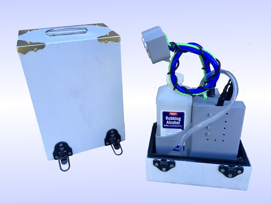
Section 2: Physical Device DesignThe primary purpose of this device is to sanitize touched surfaces by spraying a cleaning solution on those surfaces. A simple approach was used to deliver the cleaning solution. The pump was directly attached to the mister nozzle allowing it to provide a high pressure spray. When the pump is activated it draws the cleaning solution from the storage container and is dispensed in a fine mist. The quantity is controlled by the duty cycle of the pump. The pump, nozzle and tubing used are shown in the picture below.
To do this automatically, a sensors needs to be used to determine when to disinfect the surface. Different types of sensor were considered, but ultrasonic sensors were used because they are affordable and available. IR distance sensors were looked into as they are often more compact than ultrasonic sensors, but at that this time, maybe due to the pandemic, they were a very limited supply. The picture below shows the ultrasonic sensor mounted in the nozzle assembly.
With the main components selected, an enclosure was designed to house these parts. It needed to be manufacturable using a Fusion Deposition Modeling (FDM) 3D printer with a reasonable print time. A cubby for the cleaning liquid and a battery bank were also included in the housing design. This device can be mounted using zip ties or screws using the keyhole slots in the back of the housing. It can also be set on surface if tampering or theft is of limited concern. The picture below shows the 3D model of the device.
To help prepare this device for market, it was designed with manufacturability and assembly in mind. Preparing this device for assembly requires the wires and hoses to be properly connected. This prototype used screw terminals for electrical connections, but at higher volumes a surface mount connector will speed up assembly and take up less space. The nozzle is epoxied to the hoses which are press fit to the pump. With these steps done, assembly is quick.
The circuit housing is designed with a slot for the bottom of the PCB to slide into so only the two top mounting screws need to be connected. The pump has a "cup" shaped holder that it slides into with a very light press fitting. There are slots in the housing that allow for the wires to be safely routed from the pump to the PCB. Four screws attach the top cover and finish the lower assembly. The upper assembly only requires 3 screws to hold the cover plate on. For larger scaling manufacturing, snap fittings and or a cyanoacrylate glue (CA Glue or Super Glue) may be a better solution to lower assembly time and cost. The 3D rendering below shows the exploded view of the device.
The PCB was designed around the User Interface (UI) as shown in the image below. The goal was to keep it simple and intuitive. The UI consists of 4 buttons and 7 LEDs. The buttons are as follows: Power, WiFi, Spray, and Fill/Sense. The LEDs are broken up into two groups, three for status and four for level display. See the User Manual in the attachment section of this project for more information on what these buttons do and LEDs mean.
The PCB is shown in the rendering below. The design actually uses three PCBs. The first PCB is the largest and the main PCB. This PCB has the micro controller and the UI built in. The long and skinny PCB on the right side is used to capacitively sense the level of the sanitizing liquid. The final PCB, in the bottom left, was designed to illuminate the sanitized surface with a red glow to indicate to the user to wait the designated time while the cleaning liquid disinfected the surface. This feature is no longer included in this version.
The code for this device was organized using a Finite State Machine (FSM). Simply put, the machine can only be in one state at one time and uses logic to move between states. In the diagrams below, the states names are in the ovals and the logic to move between states is represented by the arrows. One benefit to this programming style is that it separates the code nicely so that different team members can program the different states fairly independently of each other.
The first diagram is the main finite state machine for this device. The logic is written in pseudo-code to make it easy to understand. The second diagram shows and explains the configuration states. This coding structure can be seen in the code attached to this project in the Main.ino file. Object oriented code was used to organize the code, written in C++ (Arduino), into classes which helps with code organization and readability.
We have identified six aspects of this device that would take this device to the next level with a little more engineering time: spray pattern, aiming spray, housing manufacturing, WiFi configuration, level sensing, and power button.
1) Spray Pattern: At the beginning of this pandemic, isopropanol was in limited supply. Therefore we did our initial testing and nozzle selection using water as our test liquid. Now that isopropanol is readily available we noticed this nozzle does not create as fine of mist using the alcohol as it did with the water. After more analysis, we found that a plug in the nozzle is the likely cause of the problem. A few solutions like using filter or a larger orifice are being considered at this time. An inline valve may be helpful to prevent the nozzle from dripping when used in a downward pointing manner. This was left out in this prototype to save space and cost.
2) Aiming Spray: Aiming the spray nozzle of this prototype works, but could be improved. The stiffening of the hose using copper wire isn't great for manufacturability as well. Our current ideas are to use adjustable plastic coolant hoses or a bend and stay housing often used for small lamps. This will both improve the easy of aiming as well as make it easier and less costly to manufacture.
3) WiFi Configuration: The current PCB does have WiFi capabilities, but our software needs more development to get this to work smoothly. Instead of hard coding each device with the network information, we started work on getting the device to broadcast it's own WiFi to allow the user to enter and save their network information. Then the device will connect to that network and allow the end user to receive notifications and usage statistics. This is still in development and just needs some more engineering time to complete.
4)HousingManufacturing: This prototype housing was designed and manufactured using a Fusion Deposition Modeling (FDM) 3D printer. This is a great method for prototypes and small scale manufacturing. At larger volumes, this housing can be optimized for other manufacturing processes as well as assembly.
5)Level Sensing: The capacitive level sensing for this device requires more troubleshooting to get working properly. It is likely a PCB design or manufacturing issue as the board acts like it is shorted out. Getting this working was a stretch goal as the device already calculates the liquid level by number of sprays dispensed. This would just remove the need for the user to let the device know when it gets a new bottle via the user interface.
6)PowerButton: The power button circuit will turn the device on, but it will only reset the device instead of powering off the device. Further troubleshooting is required to get this part of the circuit working correctly. The design for this power button circuit was from http://www.mosaic-industries.com. It is hypothesized it may be a MOSFET transistor selection issue.


Comments
Please log in or sign up to comment.