


Hardware components | ||||||
_ztBMuBhMHo.jpg?auto=compress%2Cformat&w=48&h=48&fit=fill&bg=ffffff) |
| × | 1 | |||
 |
| × | 1 | |||
 |
| × | 1 | |||
Software apps and online services | ||||||
 |
| |||||
TCS3200 is a color sensor which can detect any number of colors with right programming. TCS3200 contains RGB (Red Green Blue) arrays. As shown in figure on microscopic level one can see the square boxes inside the eye on sensor. These square boxes are arrays of RGB matrix. Each of these boxes contain Three sensors, One is for sensing RED light intensity, One is for sensing GREEN light intensity and the last in for sensing BLUE light intensity.
Each of sensor arrays in these three arrays are selected separately depending on requirement. Hence it is known as programmable sensor. The module can be featured to sense the particular color and to leave the others. It contains filters for that selection purpose. There is forth mode that is no filter mode. With no filter mode the sensor detects white light.
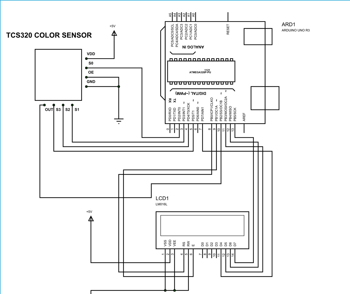
circuit diagram
In the circuit, you can observe I have only took two control pins. The contrast bit and READ/WRITE are not often used so they can be shorted to ground. This puts LCD in highest contrast and read mode. We just need to control ENABLE and RS pins to send characters and data accordingly. [Also check: LCD interfacing with Arduino Uno]
The connections which are done for LCD are given below:
PIN1 or VSS to ground
PIN2 or VDD or VCC to +5v power
PIN3 or VEE to ground (gives maximum contrast best for a beginner)
PIN4 or RS (Register Selection) to PIN8 of ARDUINO UNO
PIN5 or RW (Read/Write) to ground (puts LCD in read mode eases the communication for user)
PIN6 or E (Enable) toPIN9 of ARDUINO UNO
PIN11 or D4 to PIN7 of ARDUINO UNO
PIN12 or D5 to PIN11 of ARDUINO UNO
PIN13 or D6 to PIN12 of ARDUINO UNO
PIN14 or D7 to PIN13 of ARDUINO UNO
The connections which are done for color sensor are given below:
VDD to +5V
GND to GROUND
OE (output Enable) to GND
S0 to UNO pin 2
S1 to UNO pin 3
S2 to UNO pin 4
S3 to UNO pin 5
OUT to UNO pin 10


Comments
Please log in or sign up to comment.