


_Owo51ooXAa.png?auto=compress%2Cformat&w=40&h=40&fit=min&dpr=2)
Hardware components | ||||||
 |
| × | 1 | |||
 |
| × | 1 | |||
 |
| × | 1 | |||
 |
| × | 1 | |||
| × | 1 | ||||
| × | 1 | ||||
| × | 1 | ||||
Software apps and online services | ||||||
 |
| |||||
 |
| |||||
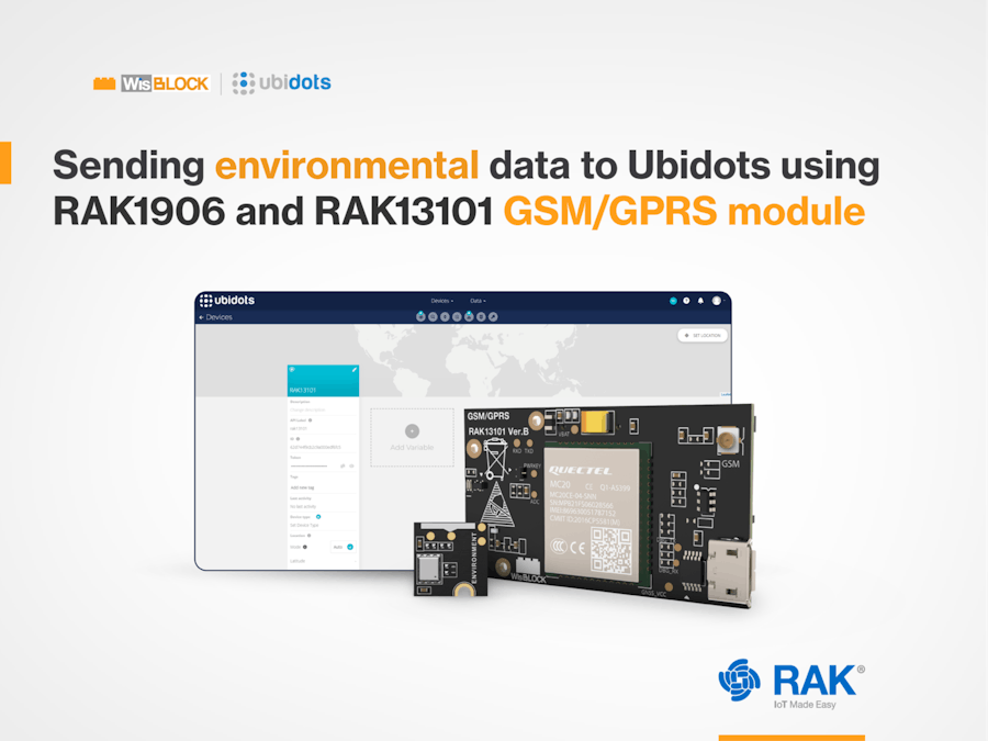
In this tutorial, we are going to develop an application, using the RAK1906, which is a sensor that allows to measure temperature, humidity, pressure and gas. We’ll also use the RAK13101, which is a Quectel mc20 wireless communication module that allows the use of a SIM Card to send data to the cloud via TCP/UDP protocol, so we can store data in the Ubidots platform.
What is TCP/UDP?TCP stands for Transmission Control Protocol. It is one of the most important protocols of the Internet and it was developed in the 70's by Vint Cerf and Robert Kahn. Like the UDP (User Datagram Protocol), it’s a protocol corresponding to the transport layer of the OSI model, which main objective is to create connections within a data network to exchange data. One of its most important features is that it guarantees the delivery of data without errors and in the same order they were sent.
Product list- WisBlock Base Board | RAK5005-O
- Nordic nRF52840 BLE Core Module for LoRaWAN with LoRa SX1262 | RAK4631 / RAK4631-R
- Environment Sensor BOSCH BME680 | RAK1906
- GSM Quectel MC20CE | RAK13101
- Battery Connector Cable/5 pcs battery wires
- A –0.3V to 4.3V Battery
- SIM Card
The WisBlock modules necessary for this IoT hardware project consist of a base, a core, a wireless and a sensor. Before anything else, let’s dig deeper into what each module does and how it works:
RAK5005-O, also known as WisBlock Base Board
This base board provides power and data for all the WisBlock modules. It supports the core, the display connection and the sensor itself. We are going to see how everything looks together later on.
RAK4631, also known as WisBlock LPWAN Module
Based on the Nordic nRF52840, an ultra-low-power MCU, this is the core of the project and contains an SX1262 Semtech LoRa® IC and BLE (Bluetooth low energy).
RAK1906, also known as WisBlock Environmental Sensor
This sensor is based on the Bosch® BME680 module and it can measure many magnitudes at the same time such as:
- Temperature
- Humidity
- Altitude
- IAQ (Indoor Air Quality)
- Gas: CO2
RAK13101, also known as GSM/GPRS Module
This module provides GSM/GPRS capability on the WisBlock platform by using the Quectel MC20CE cellular module.
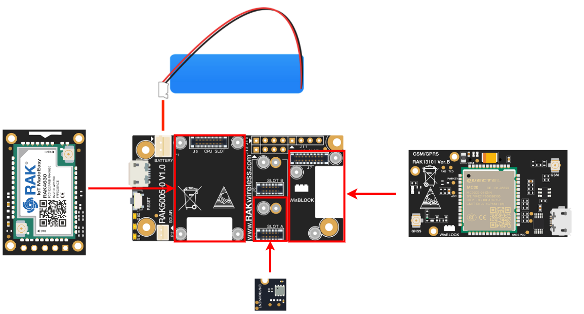
Now that you know what modules you need and how they work, let's connect the RAK4631 Core to the CPU slot.
Then, the RAK1906 sensor in the Slot A of the RAK5005-O base, both use the M1.2x3 screws.
Next, connect the RAK13101 to the IO Slot using the M1.2x3 screws.
For this module connect the antennas in their correct spot: The GPS antenna goes on the GNSS connector and the LTE antenna goes to the GSM connector just like this.
And lastly, insert the SIM card into the back of the RAK13101 module, and push it in until you hear a click.
Here is the schematic to see how the connections go.
Arduino BSP installation
For this step you can refer to our Documentation, as we need the BSP for the RAK4631 core. After you have the BSP installed, we need some extra libraries. Go to Tools > Manage libraries to open the Library Manager. Then, search them using the name and install those we highlight in the following images, or you can also find them in the code.
Check for the library name “BSEC Software Library“ made by Bosch Sensortec.
Now, let's create the account in the Ubidots platform, you can sign up here.
After creating your account you will see the onboarding page.
After the Onboarding click on the GO TO MY DASHBOARD button.
Now you will see a Demo Dashboard, click on the top part Devices, and again on Devices.
After that, you will see the Demo device. Click on the + button on the right side of the screen and on the Add new Device option.
Click on the Blank Device Button.
Then type your device name, in this case, is the RAK13101. Later click on the Check Mark on the downright of the window.
The new device will appear on the screen with the given name, click on it.
You will see your device with no data, now you will need to save the Default token for later in the firmware.
Click on your user picture and then on the API Credentials option.
The API Key wl appear and the Default Token. Click on it to show it, or simply click on the copy button you will need the token later.
Copy the firmware for this project and paste it into a new Arduino sketch. To do it, click on File>New and then paste the following code (you can also find it on our GitHub):
Take into account deleting the Void Loop and Void Setup before pasting the new code
/**
   @file RAK13101_TCP_Ubidots_example.ino
   @author harold.duarte@rakwireless.com
   @brief example of the use of the RAK13101 with the TCP protocol and the ubidots platform
   @version 0.1
   @date 2022-07-19
   @copyright Copyright (c) 2022
**/
#include <Wire.h>
#define POWER_KEY WB_IO5 //powerkey for the GPRS module
#include <Adafruit_Sensor.h> //RAK1906
#include <Adafruit_BME680.h> //RAK1906
Adafruit_BME680 bme;
// Might need adjustments
#define SEALEVELPRESSURE_HPA (1008.76) //Barometric Pressure in mbar

void bme680_init()
{
  Wire.begin();

  if (!bme.begin(0x76)) {
    Serial.println("Could not find a valid BME680 sensor, check wiring!");
    return;
  }

  // Set up oversampling and filter initialization
  bme.setTemperatureOversampling(BME680_OS_8X);
  bme.setHumidityOversampling(BME680_OS_2X);
  bme.setPressureOversampling(BME680_OS_4X);
  bme.setIIRFilterSize(BME680_FILTER_SIZE_3);
  bme.setGasHeater(320, 150); // 320*C for 150 ms
}


void setup() {

  Serial.println("MC20 power up!");
  Serial1.begin(115200); // GPRS shield baud rate
  Serial.begin(115200); //RAK4631 BR
  delay(100);

  // Initialize the built in LED
  pinMode(LED_BUILTIN, OUTPUT);
  digitalWrite(LED_BUILTIN, LOW);

  time_t timeout = millis();
  bool moduleSleeps = true;
  if (moduleSleeps)
  {
    // Module slept, wake it up
    pinMode(POWER_KEY, OUTPUT);
    digitalWrite(POWER_KEY, 0);
    delay(200);
    digitalWrite(POWER_KEY, 1);
    delay(2000);
    digitalWrite(POWER_KEY, 0);
    delay(1000);
    while (!Serial)
    {
      if ((millis() - timeout) < 5000)
      {
        delay(100);
        digitalWrite(LED_BUILTIN, !digitalRead(LED_BUILTIN));
      }
      else
      {
        break;
      }
    }
    bme680_init();

  }
}

void loop() {

  if (! bme.performReading()) {
    Serial.println("Failed to perform reading :(");
    return;
  }

  delay(15000); //waits 15 seconds to send data again
  tcp();
}


void tcp()
{
  Serial1.println("AT+QIMODE=0");  //Use AT+QIMODE command to select TCPIP Stack mode, it is non-transparent mode when AT+QIMODE=0, and AT+QIMODE=1 is transparent
  delay(200);
  ShowSerialData();
  Serial1.println("AT+QICSGP=1,\"internet.movistar.com.co\",\"movistar\",\"movistar\",0"); //Use AT+QICSGP=1,internet.movistar.com.co,movistar,movistar,0 to set APN as internet.movistar.com.co,user name as movistar,password as movistar
  delay(500);
  ShowSerialData();
  Serial1.println("AT+QIREGAPP");  //Start TCPIP task
  delay(200);
  ShowSerialData();
  Serial1.println("AT+QICSGP?");  //Check the current connecting mode(1: GPRS connecting mode£¬0: CSD connecting mode)
  delay(200);
  ShowSerialData();
  Serial1.println("AT+QIACT");  //The current connecting mode is GPRS connecting mode
  delay(200);
  ShowSerialData();
  Serial1.println("AT+QILOCIP");  //Get the local IP address
  delay(400);
  ShowSerialData();
  Serial1.println("ATV1");  //Use ATV1 to set the response format
  delay(200);
  ShowSerialData();
  Serial1.println("AT+QIHEAD=1");  //Use AT+QIHEAD=1 to add the header information when receive data
  delay(200);
  ShowSerialData();
  Serial1.println("AT+QIDNSIP=1");  //Use AT+QIDNSIP=0 to use the IP address to establish TCP/UDP session, while AT+QIDNSIP=1 is use the domain name to establish TCP/UDP session
  delay(200);
  ShowSerialData();
  Serial1.println("AT+QIOPEN=\"TCP\",\"industrial.api.ubidots.com\",\"9012\"");  //Use AT+QIOPEN=TCP,industrial.api.ubidots.com,9012 to connect to a TCP server (IP address: industrial.api.ubidots.com:9012) If return CONNECT OK means successfully connected to the remote server
  delay(5000);
  ShowSerialData();
  Serial1.println("AT+QISEND");  //AT+QISEND, send data to server, ">" from the UART indicates the following input data is considered as data to be send. After receiving ">", input data (TEST), the maximum length of the data is 1460, the data beyond 1460 will be omitted. Then use <CTRL+Z> to send data. When receive SEND OK means the data has been sent
  delay(2000);
  ShowSerialData();
  Serial1.println(">");
  delay(200);
  ShowSerialData();
  double temp = bme.temperature;
  double hum = bme.humidity;
  double pres = bme.pressure / 100.0;
  double co2 = bme.gas_resistance / 1000.0;
  String token = "BBFF-5mRERLy7jMPS9G0vHoAoTIoPz99IEQ"; //Default token from your ubidots account
  String device_name = "RAK13101"; //your device name on the ubidots platform
  String StrThree = "ubidots/1.0|POST|" + token + "|" + device_name + "=>Temperature:" + temp + ",Humidity:" + hum + ",Pressure:" + pres + ",Gas:" + co2 + "|end" ;
  Serial1.println(StrThree);//send message
  delay(1000);
  ShowSerialData();
  Serial1.println((char)26); // Ctrl+z
  Serial1.println();
  delay(200);
  ShowSerialData();
  Serial1.println("AT+QICLOSE"); //Use AT+QICLOSE to close the connecting of TCP/UDP
  delay(1000);
  ShowSerialData();
  Serial1.println("AT+QIDEACT"); //Use AT+QIDEACT to deactivate GPRS context
  delay(1000);
  ShowSerialData();

}


void ShowSerialData()// if you want to see the AT commands on the Serial Monitor
{
  while (Serial1.available() != 0)
    Serial.write(Serial1.read());
}
The token that you copied before needs to be changed on line 129, and on line 130 you also need to copy the name of your device used on the Ubidots platform, it should look something like this:
String token = "BBFF-5mRERLy7jMPS9G0vHoAoTIoPz99IEQ"; //Default token from your ubidots account
  String device_name = "RAK13101"; //your device name on the ubidots platform
  String StrThree = "ubidots/1.0|POST|" + token + "|" + device_name + "=>Temperature:" + temp + ",Humidity:" + hum + ",Pressure:" + pres + ",Gas:" + co2 + "|end" ;
Upload your firmware and reset the device once with the reset button after uploading it. After 28 seconds, you will see your information on the Ubidots platform!
You can open each variable and see the graphics with multiple options such as RAW data, Average, Minimum, Maximum, Sum and Count, the date of the sample and more info for each variable
Conclusion
We Finish! You can successfully send data over the GPRS network with your Sim Card and connect to a cloud service like Ubidots using the WisBlock modules. Also, you will be able to read many variables at once, like temperature, humidity, pressure and Co2 level. You can even connect it to your phone and read the data in any part of the world! As we always say #IoTMadeEasy.
Also, follow us on our Hackster Hub and be part of our community to keep updated with more DIY IoT projects and news.
If you want to buy our products please visit our store
Please share with us, write about your doubts and interact with us in the comment section.

_Owo51ooXAa.png?auto=compress%2Cformat&w=60&h=60&fit=min&dpr=2)


_M6kErcYJ84.png?auto=compress%2Cformat&w=40&h=40&fit=fillmax&bg=fff&dpr=2)
Comments
Please log in or sign up to comment.