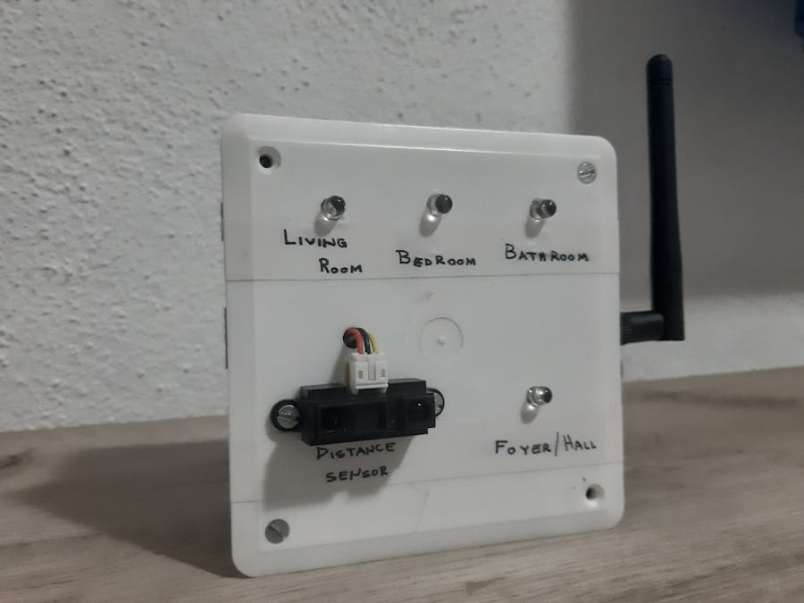
This project serves for controlling lights in house rooms with help Google Assistant, also in foyer room is distance sensor for turn on light if someone in here. For this project you need account on:
After create account on Adafruit IO page, you make your new project. Adafruit IO home page is on next photo.
In left top corner click on Actions drop down menu. In this menu click on Create a New Dashboard.
Insert name for your dashboard and description (optional). Click on Create button. After creating dashboard, click on it. In right top corner you see blue + button with name "Create a new block". After click on +, you will see popup as on next photo.
Select option marked on previous photo. After select Toggle, you need create a Feeds with name of your home rooms. My home rooms is Livingroom, Bedroom and Bathroom.
After create Feets, you need check one of your feed and click on Next step button. On this page you need insert Block Title, Button On Text and Button Off Text.
Button On and Off Text is needed for control LED lights (via Wemos D1 mini) in rooms and needed for update feed via Google Assistant.
For all Feeds you needed insert this parametres.
Step 2: IFTTT platformAfter create account on IFTTT platform (Connect with Google), you will be on home page. Click on user icon in top right corner and select Create.
On next page you need click on + This button.
After click on button, you will see page with search bar on top of page. In search bar type "Google Assistant" and select this icon bellow.
On next page you need click on Say a simple phrase block. When the next page is opened you need to fill it in with the commands that will be spoken to start command. Command for turn on light in living room is present on next photo.
Click on Create trigger. On next step you need select + That button and select Adafruit block.
After select Adafruit block, you will see page and black block on it with name Send data to Adafruit IO, select it. On next page you need select name for feed on Adafruit IO (You created this feed in Step 1).
In Data to save input:
- 1 - for turn on light
- 0 - for turn off light
Click on Create action and on next page click on Finish button.
For one light you need two this action for turn ON and turn OFF light, so for tree lights you need six commands, tree for turn ON and tree for turn OFF.
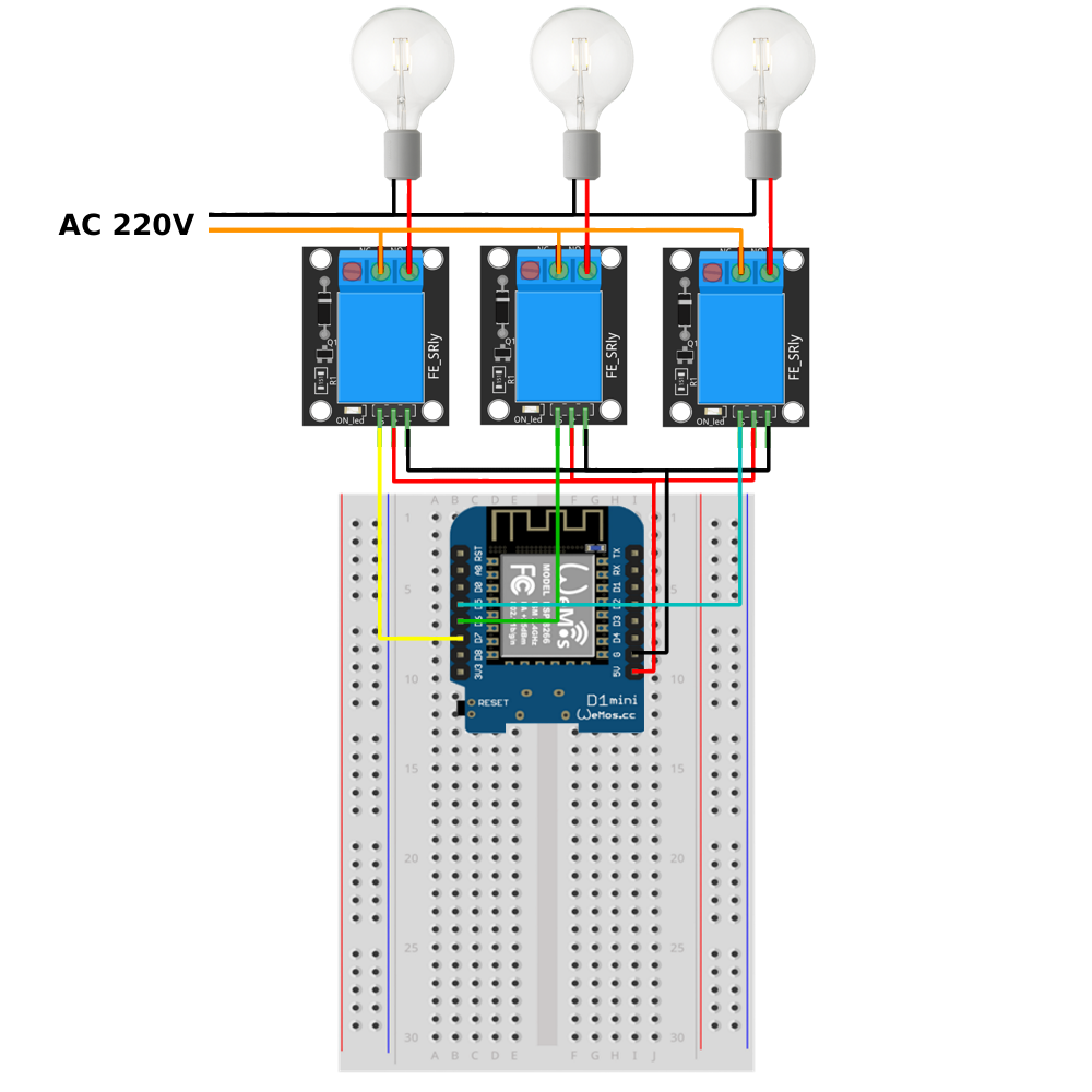
Step 3: Hardware componentsIn my project prototype instead of signal relay and AC 220V, used LED diodes and 200 ohm resistors. The same functionality is available with relays and bulbs that supply AC 220V.
On next photo, you will see schematic for project with signal relays and bulbs.
Code for upload on Wemos D1 Mini is included in attachment with name Wemos D1 Mini code.
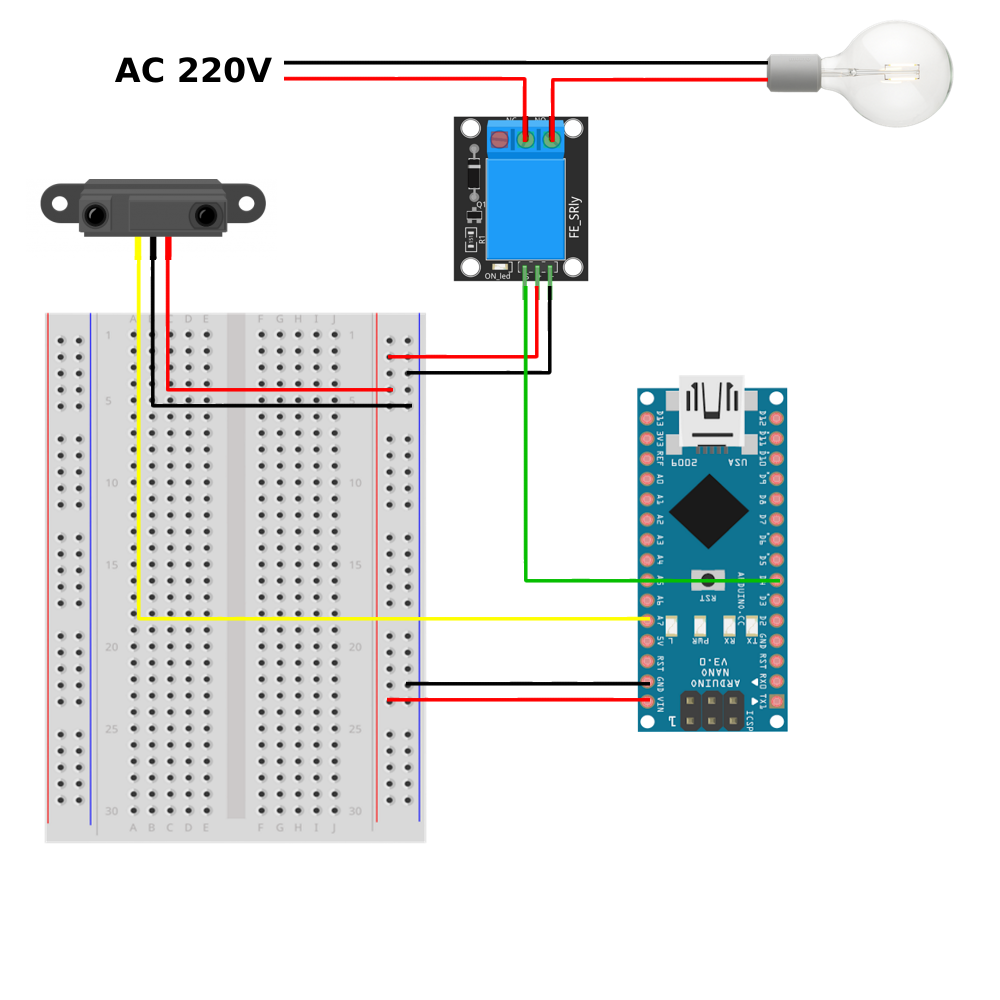
Step 3.2: Arduino Nano and SHARP 2Y0A21The other part of this project is that hall/foyer light turn on when someone is there and so remains for some time. The SHARP 2Y0A21 sensor is used to measure distance. If the object's distance from the sensor is less than 50 cm, the sensor will activate and turn on the light in the hall/foyer.
Schemtic for connecting Arduino Nano, Sharp sensor and signal relay is present on next photo.
Also in this part of project LED diode and resistor is instead of Signal relay and bulb.
Code for upload on Arduino Nano is include in attachment with name Arduino Nano code.
Step 4: Arduino IDE libraries and codeTwo libraries need to be installed for this project:
First library is used to connect with Adafruit IO platform and second library is used for read distance value from SHARP distance sensor.
Arduino IDE environment for Wemos D1 Mini board is also required and was clarified on link.
In code, first define the libraries, initialize pins and variables that will be used in the project.
#include <ESP8266WiFi.h>
#include "Adafruit_MQTT.h"
#include "Adafruit_MQTT_Client.h"
#define led1            D7
#define led2            D6
#define led3            D5
#define WLAN_SSID       "Your_SSID"   // Your SSID
#define WLAN_PASS       "Your_password"           // Your password

/************************* Adafruit.io Setup *******************************/

#define AIO_SERVER      "io.adafruit.com"
#define AIO_SERVERPORT  1883
#define AIO_USERNAME    "your_aio_username"
#define AIO_KEY       "your_aio_key"
WiFiClient client;
Adafruit_MQTT_Client mqtt(&client, AIO_SERVER, AIO_SERVERPORT, AIO_USERNAME, AIO_KEY);

/****************************** Feeds ***************************************/
// Setup a feed called 'onoff' for subscribing to changes.

Adafruit_MQTT_Subscribe livingroomlight = Adafruit_MQTT_Subscribe(&mqtt, AIO_USERNAME"/feeds/Livingroom");
Adafruit_MQTT_Subscribe bedroomlight = Adafruit_MQTT_Subscribe(&mqtt, AIO_USERNAME "/feeds/Bedroom");
Adafruit_MQTT_Subscribe bathroomlight = Adafruit_MQTT_Subscribe(&mqtt, AIO_USERNAME "/feeds/Bathroom");
AIO_USERNAME and AID_KEY is downloaded from the Adafruit IO platform. Click on green key in top right corner and copy code for Arduino IDE platform. (You will see this on next photos).
Connecting board to network is as standard as in any other project, and it is located in Arduino IDE file setup. Also same is true of the MQTT function at the end of the file below the loop.
Data from the Adaruit IO platform is read and turn on or off LED diode by the following command:
Adafruit_MQTT_Subscribe *subscription;
while ((subscription = mqtt.readSubscription(20000))) {
if (subscription == &livingroomlight) {
int led1_data = atoi((char *)livingroomlight.lastread);
digitalWrite(led1, led1_data);
}
}
To read the value from the distance sensor and turn on or of LED diode, the following command must be executed (Arduino nano code):
int dis = SharpIR.distance(); //read data from sharp sensor
if (dis < 50) {
digitalWrite(led, HIGH);
delay(5000);
}
else {
digitalWrite(led, LOW);
}To test system, you need to install a Google Assistant app on your mobile device. Login with the account, one that is related on IFTTT platform. (must be Google account).
Next video shows the full functionality of the project.


_3u05Tpwasz.png?auto=compress%2Cformat&w=40&h=40&fit=fillmax&bg=fff&dpr=2)


Comments
Please log in or sign up to comment.