


Hardware components | ||||||
 |
| × | 1 | |||
 |
| × | 1 | |||
| × | 1 | ||||
 |
| × | 1 | |||
 |
| × | 1 | |||
Software apps and online services | ||||||
 |
| |||||
| ||||||
This project was initiated and mainly developed by Prof. Ralf S. Mayer of the University of Applied Sciences in Darmstadt/Germany who left the result over to me for publishing. I think it's worth to have a look on it... an easy to build RGB sensor that can be used for any kind of color sorting machines or other purposes.
IdeaThe idea is simple: Illuminate the target object by (R)ed, (G)reen, (B)lue light and take for each a sample by a photo diode. Some calculation is required to computationally eliminate the ambient light:
- (R)ed illumination -> take sample by photo diode -> Getting value by ADC
- (G)reen illumination -> take sample by photo diode -> Getting value by ADC
- (B)lue illumination -> take sample by photo diode -> Getting value by ADC
- Calculation
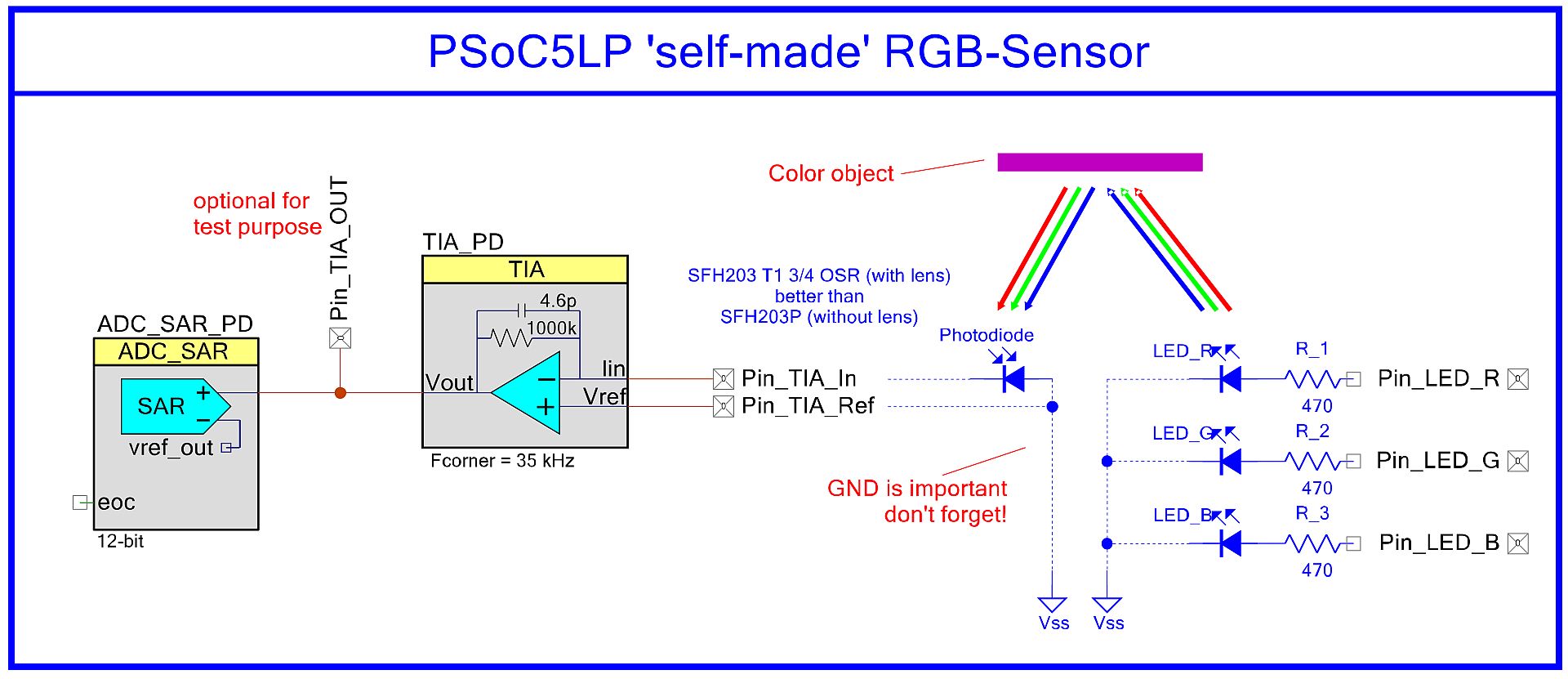
The photo diode delivers a very small current, that must be amplified extremely, and here is the benefit of Cypress' PSoC5LP as it has already a Transimpedance amplifier (TIA) implemented on chip used as current-to-voltage converter. For other microcontrollers an external OpAmp and its typical external circuitry has to be designed in. Using PSoC5LP the TIA is available on-chip. It can be selected, using the PSoC Creator IDE, dragged from the component library and dropped into the schematic.
The TIA component allows the configuration of the R/C feedback circuitry with selectable on chip resistors and capacitors.
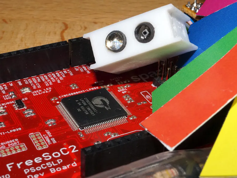
Finally, the complete schematic: ADC and TIA are integrated in the PSoC5LP, externally the photo diode and the RGB LED is connected to the I/O pins of the PSoC.
For optimization the series resistor for each color shall be evaluated by some test to get similar ADC-values for R/G/B when having a white (reference) object below the sensor.
For test purpose the Pin_TIA_OUT was added that allows to observe the analog voltage after the TIA. This is also a unique feature of PSoC that allows routing internal signals to external pins for test purpose.
SoftwareThe complete PSoC Creator project is attached. The code is documented inside. Also hints and links to related websites are given especially for the calculations respectively color transformations.
Depending on the used RGB LED (common anode/cathode) used for the illumination the correct logic levels have to be defined within the software, main.c:
#define RGBLED_ON   ( 1u )  //!< RGB-LED common cathode on
#define RGBLED_OFF  ( 0u )  //!< RGB-LED common cathode off
or
#define RGBLED_ON   ( 0u )  //!< RGB-LED common anode on
#define RGBLED_OFF  ( 1u )  //!< RGB-LED common anode off
The pin mapping is done for the Sparkfun FreeSoC2 board, but it can be easily adopted to the Cypress CY8CKIT-059, as the PSoC5LP allows an amazing pin routing, that allows to connect the external photodiode and RGB LED nearly to any user desired pin.
The UART (115200 baud, 8N1) is used to control the sensor. A help menu is invoked by < h >. The most important functions are:
h,H help
w: white balance, present a white object to calibrate
s: Sample object below photo diode (white balanced)
S: Sample object below photo diode (not white balanced)
C: Continuous sampling on
c: Continuous sampling off
X: Switch RGB LED all on (white)
x: Switch RGB LED all off
1: Switch RGB LED to red
2: Switch RGB LED to green
3: Switch RGB LED to blue
0: Switch RGB LED all off
V: Verbose output on
v: Verbose output off
First, after reset, a white calibration should be done. Place a white colored reference object below the sensor and press < w >. Now the system is ready, and you can place any colored object that will be samples by pressing < s >.
Below a snapshot of white calibration followed by three samples are given:
w -> White calibration (white reference must be below sensor!)
White balance: -> brightness: 361: R: 107, G:  67, B:  80
s -> Sample object (using white calibration)
Color is < red >
s -> Sample object (using white calibration)
Color is < blue >
s -> Sample object (using white calibration)
Color is < yellow >
For each sample the detected color is output.
The code can easily be modified to use the result for some sorting machines or whatever kind of automation process depending on colors.
That's it!
DemonstratorA second project is attached that allows to operate the sensor as stand-alone system.
For that demonstrator additionally, an external button is used to start sampling, and a WS2812B based RGB LED string is used to follow the illumination by the sampled value of the RGB sensor. In between the RGB LED string shows a running light and while sampling a RGB pattern to make it a eyecatcher for visitors.
As the demonstrator has a white floor below the sensor the white calibration is automatically processed after reset. User can place a color object and press the sample button. The result (= same color) is shown on the LED string. After a while, if no new object is sampled, the system enters a automatic mode where a running light is output. Instead of the button the demonstrator still can be controlled via UART terminal.
to Prof. Ralf S. Mayer of University of Applied Sciences in Darmstadt/Germany who initiated and realized that interesting project, that demonstrates the usage of PSoC5LP's on-chip Transimpedance amplifier (TIA) and results into a useful sensor that was already used in a marble-run project to implement a sorter mechanism. Thanks!


_3u05Tpwasz.png?auto=compress%2Cformat&w=40&h=40&fit=fillmax&bg=fff&dpr=2)
Comments
Please log in or sign up to comment.