** This is not the complete project documentation ** For better structured and more detailed documentation, please refer to the Google doc link below:
Even more detailed project documentation (Google doc)
Remote control demo video:
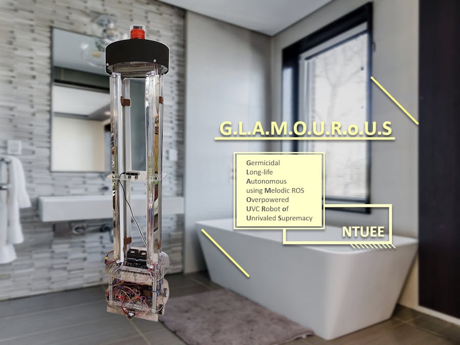
G.L.A.M.O.U.R.o.U.SGermicidal Long-life Autonomous (using Melodic ROS) Overpowered UVC Robot of Unrivaled Supremacy
AbstractUnder the threat of the COVID-19 global pandemic, our team developed an autonomous disinfection robot to help combat the coronavirus. It carries several UVC lamps with the power of disinfecting the area between 30cm~200cm height range within a1.8-meter radius when moving under the speed of 3.3 cm/s. Two horizontally mounted UVC lamps are also installed(under the robot) to specifically disinfect the floor.
The robot features low-cost, high flexibility of installation and easy assembly of hardware, and autonomous navigation, localization, and odometry memory algorithms.
Our chassis structure is built from aluminum extrusion, acrylic plates, and 3D-printed parts, which are all low cost, easily accessible, and manufacturable. Besides, M3 holes are intentionally cut on the acrylic plates to provide more flexibility of adding external modules. Just like “LEGO” has sorts of building blocks that can be easily assembled and create various works, our robot is designed to make the assembly simple and quick and to provide more extendable functionalities.
To avoid collision damage or human exposure of UVC light, depth camera, Time-of-Flight (TOF) distance sensors and passive infrared sensors (pir) are installed for active detection, while mechanical endstop, crumple zones and emergency stop switch can prevent damage in case things don't go as planned.
Since our goal is to sterilize the whole room in the most effective way, we integrated two algorithms, "left_navi" and "A*", using localization and odometry memory, to ensure the shortest path and the sterilization completeness. In this method, the robot has both remote control and autonomous navigation functions.
The room model is generated based on the Robot Operating System and the depth camera. By the depth camera d435, we can perform Simultaneous Localization and Mapping (SLAM) to build a navigation system. Using modules such as opencv and numpy, we transform the point cloud to 2D array, which helps the robot to detect objects and avoid collisions.
Brief specification- Dimension: 43.6cm×43.6cm×183 cm W×L×H
- Weight: 21.9 kg
- UV lamps : T8 40W ×4, T5 6W ×2
- Effective disinfection radius: 1.8m when velocity under 3cm/s
- Battery life: 3hr. at max power; 36hr. at standby
- Recharging time: 3hr.~ 6hr. depending on current
- Motor : 12V 35kg-cm reducer motor
- Controller : Raspberry Pi 4, Arduino Mega 2560
- Depth camera : Intel Realsense D435
- UVC lamp
The T8 UVC lamps are specified to have 9000 hrs of lifetime. When replacing those, simply rotate the lamp 90 degrees to unlock from the fixture and pick it up above the middle plate, and insert a new one. Similarly, when replacing the T5 lamps under the car, reach under the robot, rotate 90 degrees to swap the lamp out.
- Battery recharge
The battery has about 4hr lifetime when operating at full power. When the battery DOD is lower than 30%, the robot will start to navigate back to the origin point (battery charging spot), waiting to be plugged into the battery charger.
Detailed Bill of MaterialsPlease refer to the Google spreadsheets link:
Design RequirementsPlease refer to the Google spreadsheets link:
Design requirements document (Google spreadsheets)
Design suggestions achievedPlease refer to the Google spreadsheets link:
Micron design suggestions (Google spreadsheets)
Hardware/ Structural DocumentationAssembly instructionsChassis assembly
The structure of the robot is entirely made out of aluminum extrusion, acrylics plates, and 3D printed parts. Step-by-step assembly instructions are as follows:
Part 1:
1. See figure (1)(Remark: Both figure (1) and (2) are Top View). Take two 280 mm aluminum extrusions, and attach two motor mounts on each of them(Please refer to “3D Printed Parts 1.”). After that, assemble four motors and Mecanum wheels.
(Remark: The red boxes of figure (1) stand for the position of motor mounts.)
2. Connect the other two 320 mm and one 240 mm aluminum extrusion as figure (1) illustrated.
3. Fasten the 12 W ballast on the upper section of the T5 lamp & ballast holder (Please refer to “Acrylic 7.”) and two T5 lamps with reflector on the other.
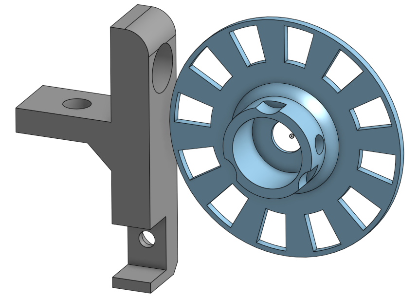
4. Bolt two bumpers (Please refer to “Acrylic 5.”), and then assemble the photo interrupter on the encoder mount and fasten the encoder disk (Please refer to “3D Printed Parts 4.”), and then fasten the encoder mount near the left-front motor mount.
Part 2:
1. Laser cut the bottom plate, and print battery mounts (Please refer to “Acrylic 1.” and “3D Printed Parts 3.”).
2. See figure (3). Fasten the battery mount.
(Remark: The red boxes of figure (3) stand for the positions to fasten battery mount.)
3. Bolt the bottom plate down to the Part 1 aluminum extrusion.
(Remark: The brown boxes of figure (3) stand for motor mounts.)
4. Paste the 1 mm rubber to the inner side of the battery mount and secure the battery in place.
Part 3:
1. See figure (2). Take two 280 mm and two 320 mm aluminum extrusions, connect them as figure (2) illustrated. Then, install four 200 mm aluminum extrusions vertically to the red boxes shown in figure (2).
2. Mount two 40 W ballasts on the T8 ballast holder (Please refer to “Acrylic 6.”). Fixed two of them down to each 280 mm aluminum extrusion.
(Remark: The blue boxes of figure (2) stand for T8 ballast holder.)
3. See figure (4). Joint Part 2 and Part 3.
(Remark: The red rectangles of figure (4) stand for 200 mm aluminum extrusions, and the blue rectangles stand for 2028 aluminum corner brackets.)
Part 4:
1. Laser cut the upper-bottom plate and speaker holder.
(Please refer to “Acrylic 2. & 8.”)
2. See figure (5). Fasten speaker holder and no fuse breaker to the upper-bottom plate, and then bolt the upper-bottom plate down to the Part 3 aluminum extrusions
(Remark: The red boxes of figure (5) stand for speaker holder, the yellow box stand for the position of no fuse breaker, the blue rectangles stand for 320 mm aluminium extrusions, and the green rectangles stand for 280 mm aluminum extrusions.)
Part 5:
- Laser cut the middle plate and camera holder (Please refer to “Acrylic 3. & 8.”).
- See figure (6). Fasten camera to the middle plate with the holder and 1720 aluminum corner brackets.
(Remark: The yellow boxes of figure (6) stand for the position of camera holder.)
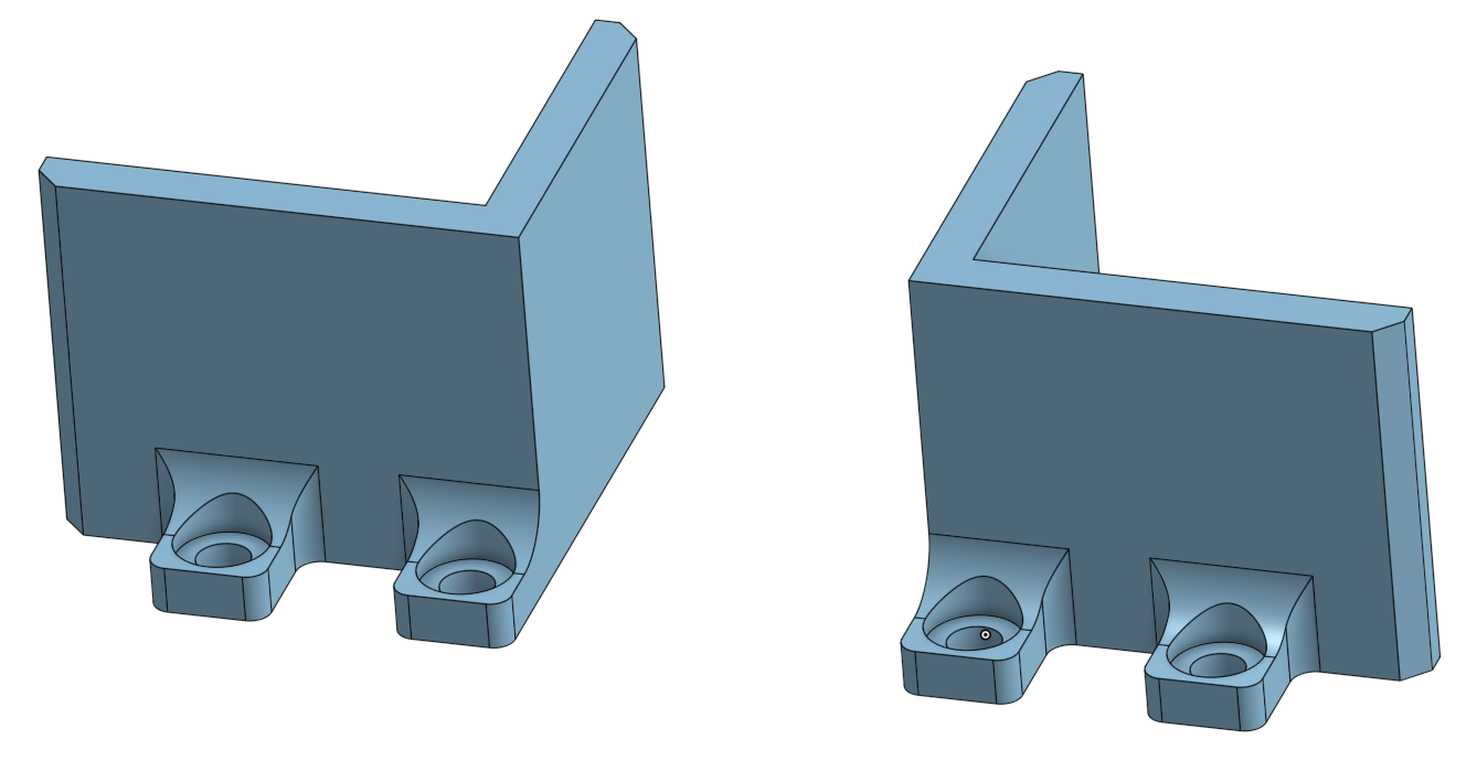
- See figure (7)(Remark: Top View). Take four 1520 mm aluminum extrusions, each of them assemble with two lamp mounts (Please refer to “3D Printed Parts 2.”)
(Notice: Mind the orientation of lamp mounts !!!)
- See figure (6). Fixed the middle plate to the middle of the 1520 mm aluminum extrusions.
(Remark: The red rectangles of figure (6) stand for 1520 mm aluminum extrusions, and the blue rectangles stand for 1720 aluminum corner brackets.)
- See figure (8) & (9). Joint Part 5 with Part 1 & Part 3.
(Remark: The red rectangles of figure (8) & (9) stand for 1520 mm aluminum extrusions, the yellow rectangles on the bottom plate (figure (8)) stand for 2028 aluminum corner brackets, and the blue rectangles on the upper-bottom plate (figure (9)) stand for 1720 aluminum corner brackets.)
- Attach lamps and lamp fixtures on the lamp mounts.
- Take two 240 mm and two 92 mm aluminum extrusions, connect them on the top end point of four 1520 mm aluminum extrusions.
Part 6:
- Laser cut the top plates (Please refer to “Acrylic 4.”).
- Assemble them. See figure (10).
- Joint the warning light on the highest plate of the top plates, and attach the PIR sensor on the lowest plate of the top plates.
- See figure (11). Bolt the top plate down to the Part 5 aluminum extrusions.
(Remark: : The yellow boxes of figure (11) stand for the m5 screw holes.)
3D Printed Parts
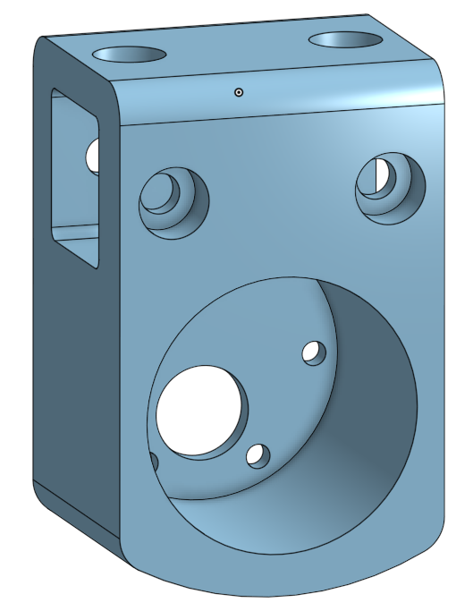
- Motor mount (*4)
Provide connection between motors and aluminum extrusions.
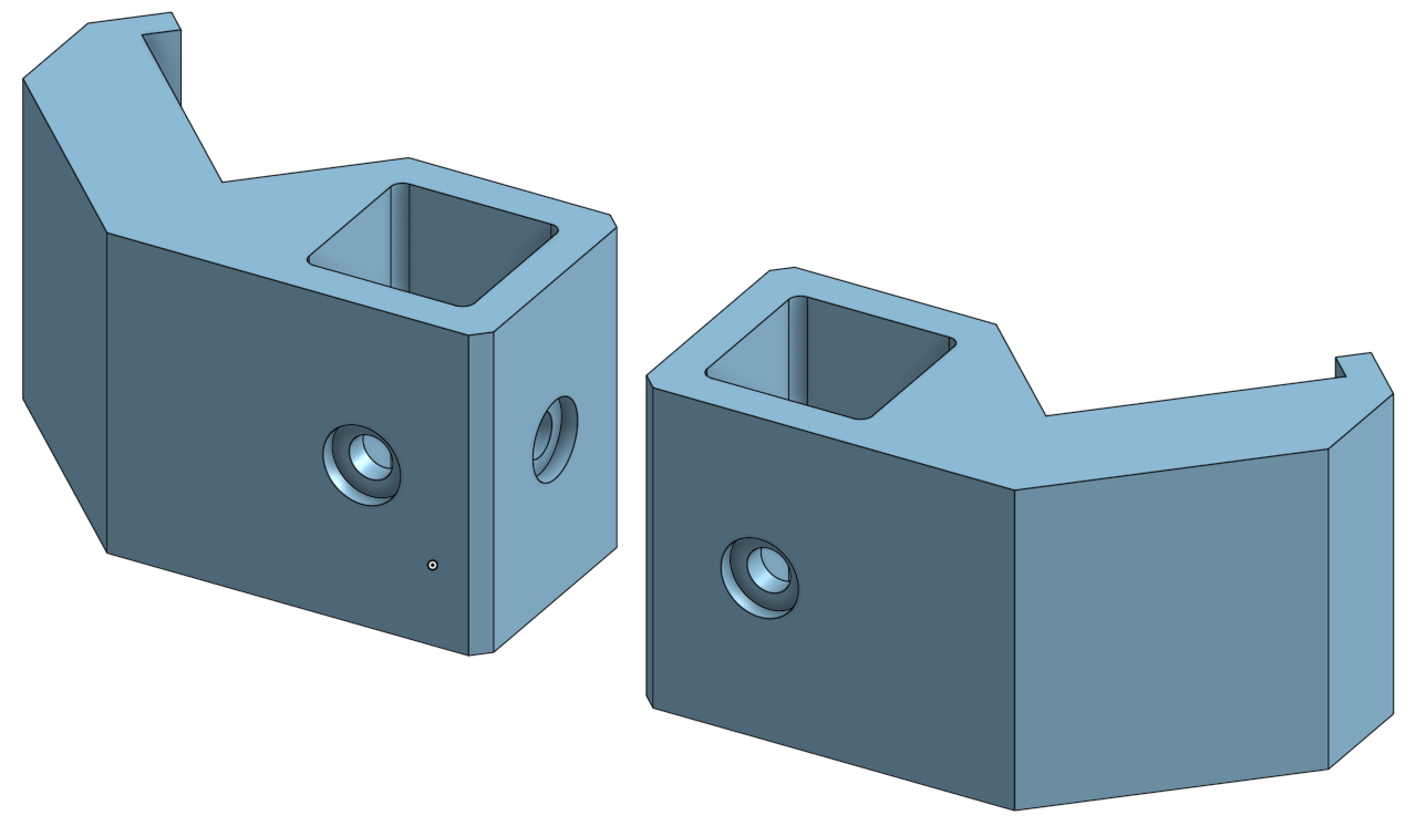
- Lamp mount (*8)
The lamp mounts provide easy installation of lamp fixtures to aluminum extrusions.
- Battery mount (*4)
1 mm thick rubber is placed at the inner side of the 3D print to absorb shock and add friction.
- Encoder mount & encoder disk (*1)
A photo interrupter paired with a 3D printed disk serves as an encoder, which has 10 degree resolution. It allows precise measurements of distance, orientation and speed.
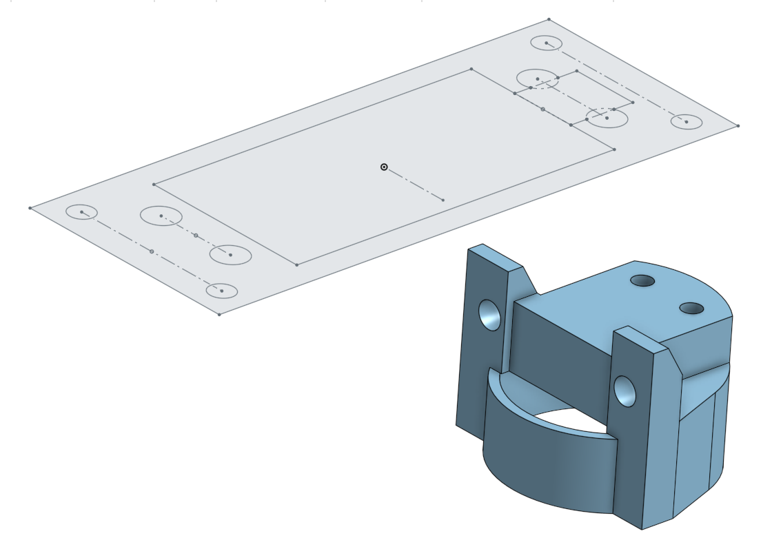
- Distance sensor on servo motor mount (*1)
Mount distance sensor on the servo. Provide more flexibility of range of
detection TOF sensor.
Acrylic
- Bottom plate
Physical foundation of most of the electrical components. We intentionally cut lots of M3 holes to freely change positions of various modules in the design phase.
- Upper-bottom plate
- Middle plate
(Lamp protection / camera holding plate
- Top plates
The top plates are made out of 3mm thick acrylic plates and EVA foam. In the unlikely event that the robot topples over, the EVA foam cushions the fall damage and the top plates act as a crumple zone.
- Front & Back bumpers
Two 5mm acrylic plates are installed on the front and back with EVA foam, approximately 3mm above ground. They prevent the robot from tipping over and block small objects from damaging motors or lamps.
- T8 ballast holder
- T5 lamp & ballast holder
Various adapters
- Camera holder
- Speaker holder
- Relay adapter
- Servo motor adapter
- Voltage step-down module adapter
- Raspberry Pi 4 adapter
- Arduino mega 2560 adapter
- Bakelite circuit board adapter
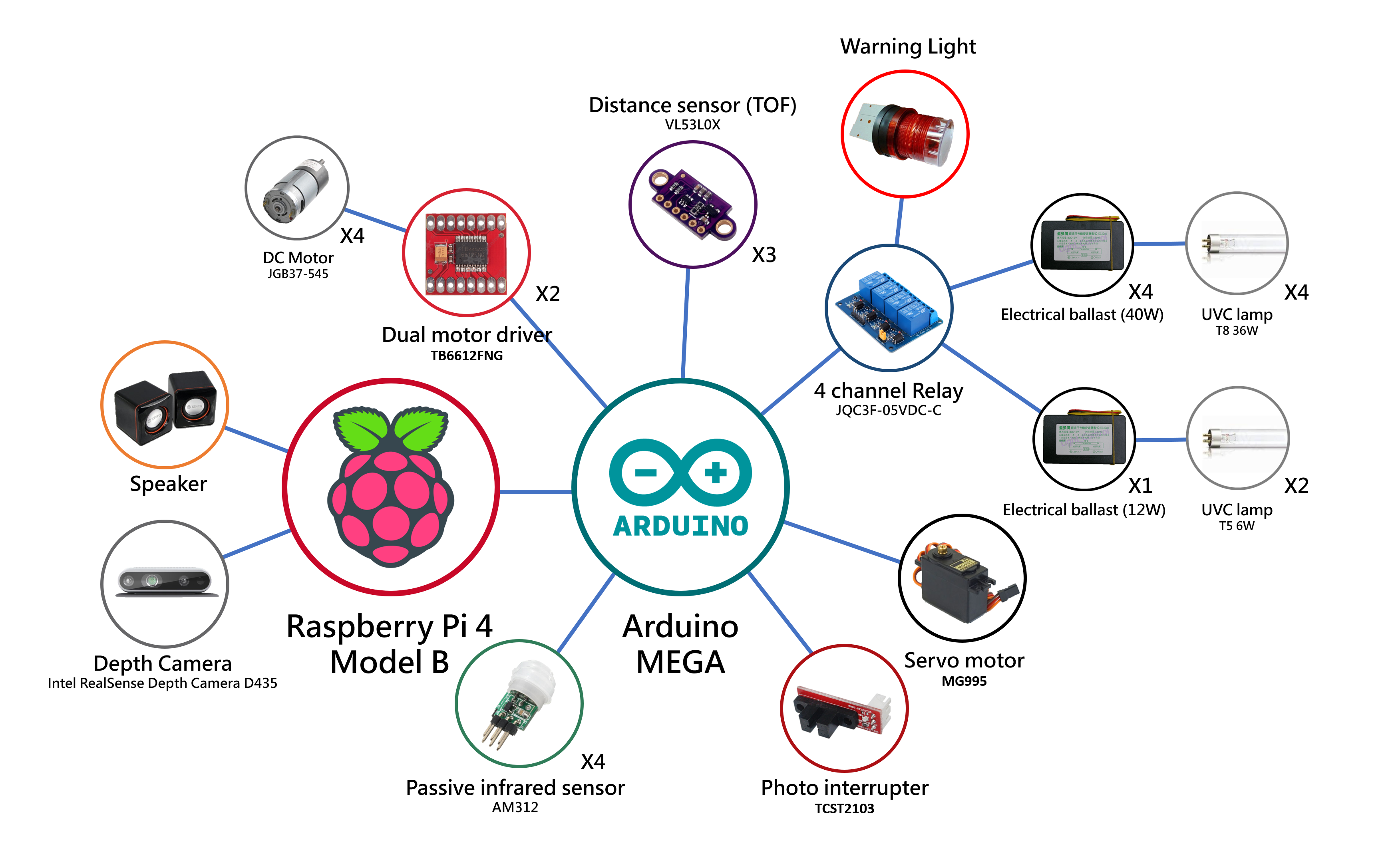
System architecture diagram
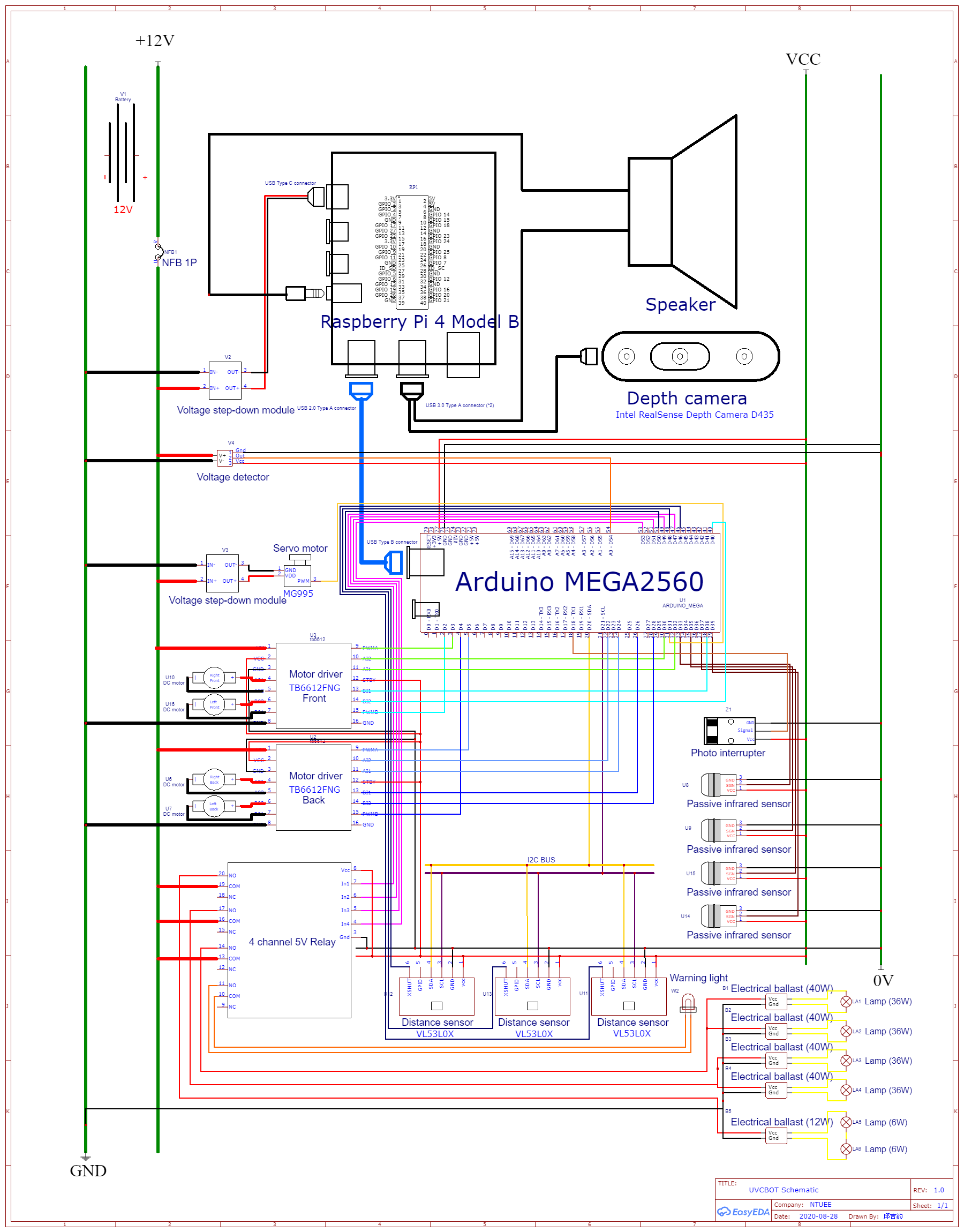
Module wiring map
https://easyeda.com/charlescjj108/NTUEEGLAMOURoUS
After finishing the chassis assembly instruction and wiring up every module, and devices described above, the last step is to assemble all of them on the bottom plate.
Refer to the figure above, bolt all the adapters to the plate including two distance sensors. In particular, the distance sensors and the servo motor adapter are assembled beneath the plate; the others are assembled above. After that, bolt all the modules on the adapters. Use some m3 copper pillars if needed. Last but not least, assemble the third distance sensor on the distance sensor on the servo motor mount (Please refer to “3D Printed Parts 5.”) which should be bolted on the servo motor as well.
Congratulations ~~~ You finished all of the assembly instruction ~~~
It’s quite easy, right?
SoftwareThe Big Picture: Data Flow
Remote Control ModeOrganization:
When using the robot in autonomous mode, run the launch file "setup_auto.launch". It calls the other two launch files and some ros nodes. Following are the files and nodes associated with it.
1. realsense_camera2_opensource_tracking.launch
This launch file is provided by the realsense camera d435. It provides a lot of information about the camera and the robot. We mainly need three pieces of information: rtabmap/cloud_map, rtabmap/localization_pose and camera/color/image_raw. We use the ros function "subscribe" to get them.
2. rosbridge_websocket.launch
This launch file contains the essential codes for the connection of ros and the website.
3. pointcloud_to_pcd
This is a node of ros, provided by ros and camera d435. The main purposes of this node are building a 3D room map by the information from rtabmap/cloud_map, and using it to make pcd files. It generates the pcd files once every fixed period of time.
4. UVbot_obstacle
This is a node of ros, controlled by a python file "obstacle.py". It uses the pcd files generated by pointcloud_to_pcd and builds a 2D array, marking the obstacles in the room. It generates a text file with the 2D array.
5. UVbot_odometry
This is a node of ros, controlled by a python file "odometry.py". It uses the information from rtabmap/localization_pose to localize the robot, and record the odometry of the robot into a 2D array. Also, it generates a text file with the 2D array.
6. UVbot_combine_map
This is a node of ros, controlled by a python file "combine_map.py". It uses the two text files generated by UVbot_obstacle and UV_odometry, and makes a jpg file, using different colors to mark the obstacles, the path of the robot and the region that has been disinfected. The jpg file will be used in the web interface.
7. camera_stream_listener
This is a node of ros, controlled by a python file "ros_image_to_jpg.py". It uses the information from camera/color/image_raw to get the real time images caught by the camera. It generates a jpg file, which will be used in the web interface.
8. rpi_to_arduino
This is a node of ros, controlled by a python file "rpiToArduino.py". It is the bridge between the web client side and the robot. Whenever a user gives instructions, it will deliver the message to the arduino (hardware) by serial.
updateImg.php and control.js are the codes associated with the web. They control the image of the web interface and deal with the user's instructions.
Autonomous ModeWhen using the robot by remote control, run the launch file "setup_remote.launch".
It calls the other one launch file and some ros nodes. Following is the file and nodes associated with it.
- realsense_camera2_opensource_tracking.launch
The same as above. However, in the autonomous mode, we don't need the information of camera/color/image_raw.
- pointcloud_to_pcd
The same as above.
- UVbot_obstacle
The same as above.
- UVbot_odometry
The same as above.
- UVbot_combine_map
Mostly the same as above. In the autonomous mode, the integrated map is used to check the places that should be disinfected, not for the user interface, so the output file is a text file with a 2D array.
- UVbot_main
This is a node of ros, controlled by a python file "main.py". This node contains the "left_navi algorithm" and "A* algorithm", which will be introduced later. The purpose of this node is to decide where to go and how to go, and to deliver commands to arduino (hardware) using serial. The final goal is to sterilize the whole room with the shortest path.
ROS IntroRobot Operating System (ROS) is an open-source, meta-operating system for robots. It's framework gathers a bunch of software tools for developing a robot. With this framework, we can build and reuse code between robotics applications, which helps us save a lot of time.
In this project, we use four main nodes for the SLAM process: "realsense2_camera", "imu_filter_madgwick", "rtabmap_ros" and "robot_localization". We use python programs to create subscriber nodes and get the important information from the depth camera.
ArduinoThe role of Arduino
We use an Arduino Mega 2560 for this application. It is powered by the USB type B port connected to our Raspberry Pi, and uses serial communication (UART) over USB to communicate with Raspberry Pi.
Arduino controls 4 DC motors, a servo motor, and receives velocity/distance/degree data from the encoder, and distance information from three TOF distance sensors. The complete source code and detailed explanation is in README. https://github.com/noidname01/UV_Robotic_Challenge-Software/tree/master/arduino_main
There are five files in the arduino, which are:
arduino_main.ino: reads sensor values, updates encoder and servo position and receives Raspberry pi commands in the main loop.
encoder.h: monitor the distance/degree the robot has moved since the command has been delivered
motorControl.h: controls the motion and velocity of motors
servo_sweeper.h: sweeps the servo motor by a small degree on every loop
tof.h: update the distance readings of the three distance sensors
MappingSLAM with D435
Simultaneous localization and mapping (SLAM) is the computational problem of constructing a map of an unknown environment while simultaneously keeping track of an agent's location within it. To SLAM with D435 camera on ROS, we use nodes such as realsense2_camera, rtabmap_ros, and robot_localization. By this technique, we will get a map of the room, and the navigation process can be carried out.
Map ProcessingOdometry
- What
Odometry is a type of data that records the track of our robot.
Usually it is generated from motion sensors which helps correct the error caused by the motors, but in our case, the position of our robot would be marked on the map of the room, and since the map is generated from the camera (Intel RealSense Depth Camera D435), we choose to record our localization data from the camera, too.
- Why
Historical track is an essential and basic part for our whole project, it will be used for further application.
- How
First, we use rospy, the communication system in ROS, to capture the localization data message published from the camera.
After receiving the position data, since we’re running our programs on Raspberry Pi 4 rather than normal laptops or computers, our aim is to transmit a minimum-sized array that records the status of each grid: visited, disinfected or not yet disinfected. We adjust the size of the array by checking if the new point overflows and get the position of origin in the array.
The data we receive are discrete points. Since our robot does not move so fast and its track would not be a curve, it is reasonable to assume that the real trajectory is the connection of two points, we can then update the disinfected-map and visited-map respectively, and add them up to overlap the information.
Finally, output the text file including odom_map array, the coordinates of origin point, map size, and present coordinates for further application.
By the way, we have a testing function that can manually enter coordinates and output a jpg image file (image including more information would be generated in other programs).
The following is the screenshot of the testing text file and image file.
Obstacle
- What
This program receives the.pcd file generated by another ROS node, pointcloud_to_pcd, with the information obtained from realsense_camera2_opensource_tracking.launch.
It changes the 3D cloudpoint map to 2D array, using '3' to mark the obstacles that may block the robot, and '0' to mark the road. The purpose of the program is to generate a text file with a 2D array to represent the room map.
- Why
In the autonomous mode, we hope the robot to sterilize the whole room with the shortest path, which means to disinfect the room in the shortest time. To plan the path, the algorithm needs the map of the room.
Moreover, in the remote control mode, the user can't stay in the room, so they have to know the location of the obstacle. Thus, we want to use this program to generate the obstacle map.
- How
We first create a node for launching a program in ROS, and run the main function.
The camera and the ROS SLAM function generate.pcd files once every unfixed period of time. After checking there exists.pcd files in the dictionary and captures the file, make_obstacle_map() will generate a 2D array composed of 0 and 3, where '3' indicates obstacles; '0' the rest, then it will output a text file obstacle_map including the array and related information, including the size of the array and the origin coordinate of the robot.
Following is how we achieved it.
First, read a.pcd file, and get the point cloud data of the map. The point cloud data begins with some overall information which is not important in our case. Following that is points' information, including x-axis, y-axis, z-axis and color. This is a 3D point cloud data file.
The color of the point is not important. Because the robot is only 1.8 meters tall, we just have to care about the obstacle shorter than 1.8 meters, which means z<1.8. The file obstacle_tmp.txt records the obstacle that is shorter than 1.8 meters.
Then the point cloud data file becomes 2D.
Second, read the file obstacle_tmp.txt and find the range of the pointcloud. Construct an array representing the map, each of the element represented a 2cm*2cm space. The elements are denoted by the number of the points in their representing space.
There are errors from the camera and the point cloud generator, so the array now may not be the real map of the room. So we try to modify the obstacles and make the map more smooth.
If a space is around a lot of points, it means that the space is highly possible to have an obstacle on it, so we check how many points are there around every 2cm*2cm space.
For every element, count how many points are around the representing space, and add the number to its own number. If the final number is larger than a variable (thres), denote the element by '3', otherwise denote it by '0'.
After the process above, an obstacle map has been mainly made. However, because the array represents a rectangle, and the condition outside the room wall can't be detected by the camera, we have to mark out the space outside the room.
The method we use is to detect from four sides of the map. Denote elements by '3' until we detect one element that is '3' originally.
Finally, write the array to the file obstacle_smooth_fill.txt. The two lines in the bottom of the file represent "the origin of the robot" and "the size of the room".
Combine_map
- What
This program receives the information from odometry.py and obstacle.py, and output the integrated text file and image file, both showing each grid's present state: obstacle (e.g. the wall), visited, disinfected, or not yet disinfected.
- Why
The integrated information is critical because our goal is to clean the entire room and avoid repeated or redundant routes. By updating and classifying each grid's status, we can achieve dynamic route planning, also visualize the track and disinfection progress for users to check in real time.
- How
We first create a node for launching a program in ROS, and run the main combine_map() function.
combine_map() generates a numpy array comprised of 0, 1, 2 and 3, where
'3' indicates obstacles;
'2' represents that this grid has been visited;
'1' for disinfected but not visited;
'0' the rest.
Then it will output a text file including the array, related information, and a jpg file according to the array, where
black ([0, 0, 0]) represents obstacles;
yellow ([0, 255, 255]) represents path;
purple ([255, 0, 0]) for regions that have been disinfected;
white ([255, 255, 255]) for regions that haven't been disinfected.
Following is how we achieved it.
First, read the text files generated from odometry.py and obstacle.py, then store the data we need respectively:
1. the map array
2. the origin (initial point) coordinates in the array
3. x and y size of the array
4. the present coordinate in the array
Since the data transmitted is the minimum array, the size and coordinates of the two arrays might not be identical. Thus, to integrate the arrays, we overlap the origin points and adjust the size of the array.
After getting an array with proper size and coordinate system, we can fill in the value for each grid with some translation. Finally, generate the text file and jpg file.
Below is an example of combime_map.jpg
We use React.js and Bootstrap to build up our website, it has two pages, control and info, and use rosbridge_server to create a communication bridge between js and ros topic, making the remote control come true.
Remote controlThe upper image is the map we created, which will update over time and display the walls, the odometry, the area where has been disinfected.
The lower image is the stream of camera, enabling users to remotely control the UV robot.
The right part is the console, users can pause(center button), left and right, forward and backward to control the actions of the robot.
The bulb sign can control lights, on and off.
This website will determine what information returned from ros and alert corresponding messages and change the appearance of the website.
Info
Info page will display how much energy that the battery still has, and render it on our website.
The bottom area is the record of actions.
To ensure the UV robot works properly, users have to place it at a corner of the room. The robot will firstly adjust its direction so that the wall is on the left of itself, and then start to move. The navigation strategy in stage 1 basically is to walk along the wall (or the area the robot has disinfected) while simultaneously recording the area the robot can't enter (ex: obstacles), the path the robot has walked through, and the area the robot has disinfected on the map array. The robot will finally stop at a certain position in the room.
In stage 2 the robot will check if there's any area not disinfected on the map array, and then will navigate to the nearest part to disinfect it. The navigation method in this step is to find the best path with A* algorithm. After entering the not disinfected area, the robot will move in the same manner with that in step1.
The robot will perform step1 and step2 alternately until almost every part of the room is disinfected.
Stage1:
left_navi
This method is to ensure that the UV robot walks along the wall (or the disinfected area), and the wall will be on the left with distance=10cm. If the robot finds itself getting apart from the wall, it will turn left to find the new best direction. If there's any obstacle ahead, it will turn right to bypass the obstacle. Meanwhile, the robot will keep the distance between itself and the obstacle at least 10cm apart. In the first lap, the robot will walk along the wall. After visiting the room, it will identify the area it has disinfected as the 'wall' in the next lap and will walk along the inner bound of such area.
The robot checks a specific point with its location shown in the figure below to ensure that it walks along the wall. If there's nothing at such point, it will first turn left 90 degrees and then turn right slowly to find the best new direction to go.
Stage2:
find_unknown_area
In terms of finding the nearest point of the area that hasn't been disinfected, the robot will check the map array it recorded with the greedy algorithm. It firstly checks if there's any not disinfected point 1 unit far away from itself(for convenience, we use L1 distance). If no, then checks that 2 units away from itself. The search distance will increase until the robot finds any point not disinfected.
Shortest Path Algorithm: A*
A* is a graph traversal and path search algorithm, which is often used in many fields of computer science due to its completeness, optimality, and optimal efficiency.
The picture above shows that all the grid and its corresponding heuristic cost. The way to
calculate it depends on how much we know about the map. For example, the picture above
indicates that we can take the distance between the grid itself and the goal and then round it up.
We adapt this method to calculate our heuristic cost in our path planning algorithm.
First, we search around the start point, find the grids that can be next searching start point, and sort it by heuristic weight plus how many steps it take to reach this grid from start point, less first.
Second, choose the first grid in the searching queue and then search its neighbor. Loop over and over again, until we find our goal. It will return a list containing all the grid on the shortest path. Then convert these points into commands and move our robot, our work is done!
Collision/Fall damage protection
- Front & back bumpers
Two 5mm acrylic plates are installed in the front and back with EVA foam, approximately 3mm above the ground. They prevent the robot from tipping over and block small objects from damaging the motors or lamps.
- Heavy battery
Heavy battery lowers the center of gravity, providing good stability.
- Downwards pointing distance sensors
Two distance sensors are mounted directly in front of the front wheels, pointing downwards. When encountering an edge (e.g. stairway), they send a signal to stop the robot.
- Front pointing distance sensors
A servo motor is mounted near the ground with a distance sensor attached to it. The sensor constantly scans a 120-degree angle in front of the robot when moving forward. When approaching a low obstacle which can’t be detected by the depth camera, the sensor picks it up and appends the obstacle to the map generated by the camera.
- Crumple zone
In the unlikely event of the robot toppling over, the top crumple zone would smash onto the ground before the UVC lamps could take damage, if any at all.
- Mechanical endstop (not yet implemented)
Endstop installed on the bumper directly cuts off the power supply of the motor as a last resort braking system.
- EVA foam
On the top crumple zone and under the front and back bumpers, we wrap EVA foam around to add extra security
Human UVC exposure precaution & detection
- Audio & visual warning
Before the disinfection procedure begins, the warning light flashes and the speakers make a loud siren wail followed by the warning speech: “DISINFECTION PROCEDURE ABOUT TO BEGIN, PLEASE VACATE THE AREA UNTIL UV LIGHTS ARE OFF”.
At all times when the UVC lamps are on, the warning lights will keep on flashing, and the speakers will repeatedly say:”DISINFECTION IN PROGRESS, KEEP OUT! KEEP OUT!”.
- PIR sensors
Four passive infrared (pir) sensors are installed on the top (crumple zone plate, about 160 cm in height). Whenever human motion is detected, the power supply to the UVC lamps is instantly cut off, robot movements are paused, and the speakers aggressively shout: ”WHAT DID I JUST TELL YOU?? WANNA GET SKIN CANCER OR WHAT? GET THE HECK OUT OF HERE! NOW!!” if absolutely needed. Disinfection will continue once all humans are in the clear. Starting with the warning routine listed above.
Circuit fail-safe design
- Active HIGH design
The lamps will turn on if and only if all sensors (i.e. pir sensors, distance sensors) are properly running and output a HIGH signal. In other words, if any sensor fails or any wire gets loose, the lamp will not be turned on.
- Overcurrent protection
A no fuse breaker is installed to prevent accidental short circuits.
CalculationsThe 3D CAD files are designed entirely on the online platform Onshape:
Source CodeGithub link to all of the source code:
https://github.com/noidname01/UV_Robotic_Challenge-Software.git
ReferencesSLAM with D435i
https://github.com/IntelRealSense/realsense-ros/wiki/SLAM-with-D435i
A* algorithm
ROS tutorial
https://ithelp.ithome.com.tw/users/20112348/ironman/1965
ROS wiki:ROS tutorial
http://wiki.ros.org/ROS/Tutorials
Wikipedia:Ultraviolet germicidal irradiation
https://en.wikipedia.org/wiki/Ultraviolet_germicidal_irradiation
How robots make their route planning
https://www.google.com/amp/s/www.inside.com.tw/amparticle/6542-robot-cleaner
Compiling librealsense for Linux using Ubuntu
https://dev.intelrealsense.com/docs/compiling-librealsense-for-linux-ubuntu-guide
Github:librealsense
https://github.com/IntelRealSense/librealsense/blob/master/doc/installation_raspbian.md
Robot Operating System (ROS)
http://www.iceira.ntu.edu.tw/project-plans/195-robot-operating-system-ros
ROS wiki:Ubuntu install of ROS Melodic
http://wiki.ros.org/melodic/Installation/Ubuntu
Tutorial:ROS and MAVROS installation in Raspberry
https://junmo1215.github.io/tutorial/2019/07/14/tutorial-install-ROS-and-mavros-in-raspberry-pi.html
Github:realsense-ros
https://github.com/IntelRealSense/realsense-ros
introduction to SLAM
SLAM: Simultaneous Localization and Mapping
http://ais.informatik.uni-freiburg.de/teaching/ss12/robotics/slides/12-slam.pdf
RealSense™ for SLAM and Navigation
https://intel.github.io/robot_devkit_doc/pages/rs_slam.html
How to build a map with Google Cartographer SLAM algorithm
https://blog.techbridge.cc/2016/10/29/ros-cartographer-slam-basic/
ROS wiki:navigation
http://wiki.ros.org/navigation
ROS wiki:cob_tutorials
http://wiki.ros.org/cob_tutorials/Tutorials/Navigation%20%28slam%29
ROS wiki:base_local_planner
https://wiki.ros.org/base_local_planner?distro=groovy
ROS wiki:NetworkSetup
https://wiki.ros.org/ROS/NetworkSetup
ROS wiki:Remote monitoring and control
http://wiki.ros.org/robotican/Tutorials/Remote%20monitoring%20and%20control
ROS wiki:rosserial_arduino/Tutorials
http://wiki.ros.org/rosserial_arduino/Tutorials
RTAB-Map



_wzec989qrF.jpg?auto=compress%2Cformat&w=48&h=48&fit=fill&bg=ffffff)





Comments
Please log in or sign up to comment.