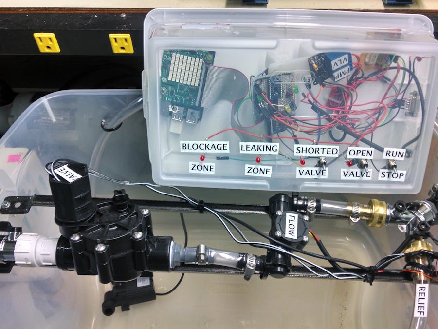
We built an irrigation controller that detects and isolates faults such a leaks, blockages, and broken valves using a Raspberry Pi running Windows 10 IoT core passing messages to the Microsoft Azure cloud service. Farm and home owners can get a push notification when something breaks or leaks, and using evapotranspiration data from the water district, can optimize water use. Farm and home owners would no longer have to "walk the lines" (inspect the system when it is running) because problems are automatically detected and the user is immediately made aware of a problem.
When and Where:We finished off the prototype at the Microsoft IoT Hackathon in Orange, CA on 2/20/16 and took first place for a working project that had potential for environmental impact and used Microsoft products. It was a lot of work but much fun! With me were TimS who did the heavy lifting in Windows IoT and John O'Connor who made major troubleshooting breakthroughs and all the Node.js code for the simulator and front-end Azure GUI. I designed the hardware, demonstration tub (pictured), and test box with Raspberry Pi and test software.
Concepts:We would like to be able to install this system on existing irrigation systems. To do that, installers would basically replace the controller and would have to install flow meters for each area. Wires for the flow meters would need to be installed. In our system, an "area" is comprised of multiple "zones". Zones are basically a single valve connected to multiple sprinkler heads. A zone is the lowest entity that we can isolate to, such as a section of your lawn that turns on at the appropriate time. Usually, multiple valves are located in clusters distributed around property. Our concept is that each cluster of valves, or "area", will have a flow meter installed. In this system, it is assumed that only one valve per area is on at any given time.
How it works:The Raspberry Pi is the local controller that talks to the Azure cloud. There is a message protocol that we developed in JSON that goes between the cloud and the controller. For the hackathon, we used Device Console to send and receive raw JSON messages, so, the front end has not been developed yet. So, theoretically, from Azure, users could (if we finish the code) set the watering schedule and use evapotranspiration and weather data to recommend watering schedule changes. On the controller side, the Raspberry Pi receives watering schedules from Azure and does the labor to turn valves on and off. If there is a failure, such as abnormally high water flow (leak), abnormally low water flow (broken wire or valve or clogged filter), or an overcurrent from a valve (shorted valve), then messages are sent back up to Azure which then notifies the user.
Hardware:For the hackathon, the Raspberry Pi simply uses GPIO pins to 1) measure flow, 2) control valves, and 3) sense overcurrent (a manual switch). In the real world, many improvements need to be made. 1) Measure Flow - the flow meter is on each "area" or cluster of valves and sends a 5v DC pulse train back to the controller. If the flow meter is more than about 50 feet from the controller, an RS485 differential signal is needed to get the distance. +5vdc, ground, and signal needs to be run to each flow meter. 2) Controlling Valves: valve relays are usually in a box outside of the building and we want the Raspberry Pi to be inside. For a professional system, PLC relays operating on a ModBus protocol would be used. Our hackathon system did not develop the ModBus interface. Depending on the distance between the Raspberry Pi and the PLC system, it is likely that an RS485 or other wireless connection be established to the PLC valve relays. 3) Overcurrent sensing: valves typically run on 24vac for efficiency, but in our system, it is easier to measure a shorted valve using a DC current sensor. Valves will operate correctly on 12vdc, therefore, the valve power is switched to 12vdc and current sensors are installed on the power supply (not on each valve). The current sensor requires an I2C bus and 3.3 to 5v level shifting for the Raspberry Pi, therefore, the Raspberry Pi can't be very far from the power supplies. If there is more than 10 feet, then, there needs to be an Arduino or other device that can transmit current sensing information to the Raspberry Pi.
Our major hurdles:Working with Microsoft IoT and Azure was tricky at times and we had never used it before, so, good learning experience. We kept getting an "unauthorized exception" which we beat our heads against for two weeks. Come to find out, the reason for it was because the date/time on the Pi didn't match Azure's date/time - an opportunity for Microsoft to improve their error handling. We also had network problems due to router security which wasn't very obvious. Once we started using a 4g hot spot, everything started working.
Future plans:We would like to upgrade the demonstrator so that we can show it to other groups and use it as a launch pad for an open source project. The hardware was totally hacked over a weekend with wires solder tacked onto pads, loose connectors, and the slightest earthquake could cause the 24volts to short to the Raspberry Pi 3.3 volt line which would not be good. Therefore, we need to tighten up and make reliable the hardware and we need to finish the user interface so that everyone can understand how it works. Beyond that, we need to get a PLC based system working so that it can be installed on professional farms and nurseries.


Comments
Please log in or sign up to comment.