


Hardware components | ||||||
| × | 1 | ||||
| × | 1 | ||||
| × | 1 | ||||
| × | 1 | ||||
| × | 1 | ||||
 |
| × | 1 | |||
 |
| × | 1 | |||
| × | 2 | ||||
| × | 1 | ||||
| × | 1 | ||||
| × | 1 | ||||
| × | 1 | ||||
Software apps and online services | ||||||
 |
| |||||
| ||||||
Hand tools and fabrication machines | ||||||
 |
| |||||
| ||||||
This is a fun and easy project for beginners looking to get started with basic electronics and Internet of Things (IoT).
The aim of the project is to make a simple electronic car that you can control from your phone (using components like the ESP32 and software like Blynk).
MOTIVATIONThis project was made by the planning committee of SST Makerspace. The mission of SST Makerspace is to present an opportunity for students to have a new learning experience through extracurricular experiential learning. It is designed to cultivate healthy competition, teamwork, and problem-solving skills among PAU engineering students and any PAU student interested in Robotics, Embedded systems and Internet of Things (IoT).
OUTLINESTEP 1: Building the Chassis
STEP 2: Connecting the components
STEP 3: Setting up the Arduino IDE (libraries and board)
STEP 4: Writing the code
STEP 5: Setting up IoT control for the car (using Blynk)
STEP 6: Uploading the code to the ESP32
STEP 7: Controlling the car from your phone
STEP 1: Building the ChassisThe first step is to build the chassis for the car. To do so, follow these sub-steps:
- Get a flat surface: Get a flat material like a wooden board or a flat plastic.
- Attach the castor wheel: Use the glue gun or superglue to attach the castor wheel in the front and center (to serve as the front wheel of the car).
- Attach the geared motors and car tyres: Before attaching the geared motors to the chassis, solder jumper wires (or tie the wires) to each part of the geared motor. This is necessary to allow you connect the geared motors to the motor driver. After attaching the jumper wires to the geared motors, glue the motors towards the back corners of your flat material such that the jumper wires attached to the motor are facing the outer part so that they can be raised from the side of the car to connect to the motor driver that will be at the top. After gluing the geared motors, you can attach the wheels to them.
- Attach the breadboard: Most breadboards have a backing layer that prevents the metal clips from falling out. The backing is typically a layer of sticky, double-sided tape covered by a protective layer of paper. You can either remove the protective layer of paper and stick it on to the top of your chassis (the side opposite to wear you attached the castor wheel and the geared motors) or you can tape or glue the breadboard to the chassis.
- Attach the battery holder: The primary function of a battery holder is to keep cells fixed in place safely and securely while conveying power from the batteries to the motor driver. For the battery holder used, since there are two batteries you'll have to solder a wire at the back to connect the positive terminal of one battery to the negative terminal of the other (connect them in series). Note that not all battery holders would require you do that. An image is attached below showing the soldered wire on the back of the battery holder. You can also tape the wire on instead of soldering. After doing so, attach (using super glue or the glue gun) it to the top of the chassis.
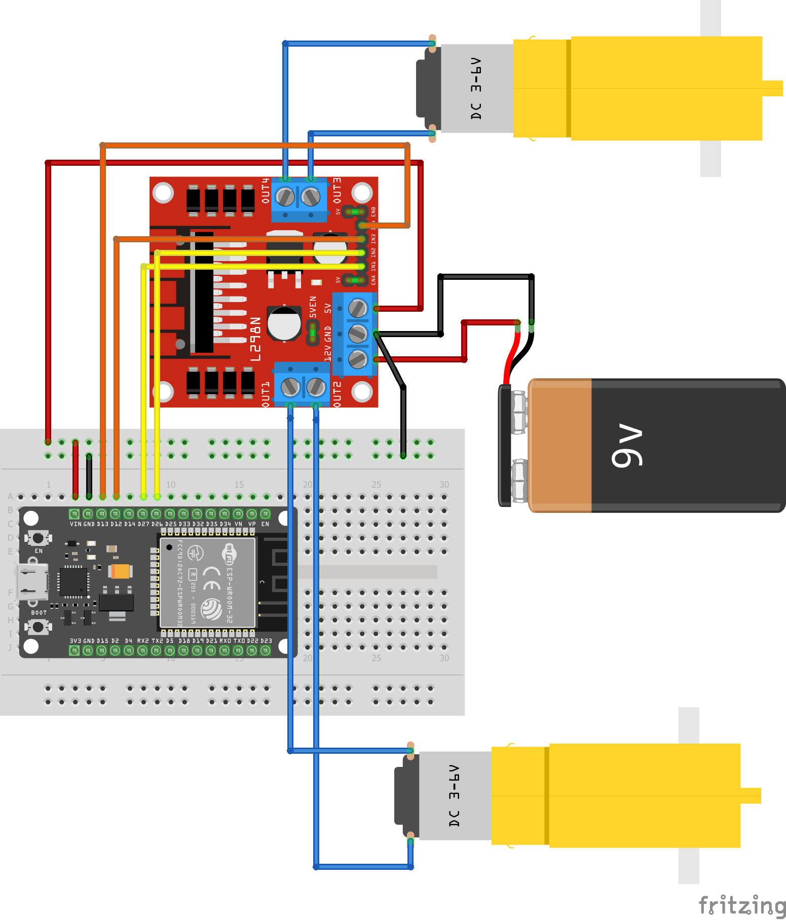
The next step is to connect the components. The components are connected as shown in the in the attached Fritzing Circuit Connection Diagram.
The connections are outlined below:
- Connect the battery holder to the L298N motor driver: Connect the wire from the positive terminal of the battery holder to the 12V input and the wire from the negative terminal of the battery holder to the GND on the motor driver. You'll have to unscrew the 3.5mm-pitch screw terminals on the motor driver (using a small screw driver) and screw them back once you have inserted the wires. Don't put your batteries into the battery holder
- Place the ESP32 on the breadboard: Place it in such a way as to leave a path open for connections on the side of the ESP32 that has the VIN pin. Ensure the ESP32 is firmly inserted.
- Connect the ESP32 power pins to the L298N motor driver: Connect one end of two male-male jumper wires to the VIN and GND pins of the ESP32 (that is to the rails on the breadboard where the VIN and GND pins have been connected to) and the other end of the jumpers to the screw terminals of the L298N motor driver for 5V and GND respectively.
- Connect the geared motors to the L298N motor driver: Connect the two soldered or tied wires from each of the geared motors (attached on either side of the chassis) to the two screw terminals available on either side of the motor driver (adjacent to where the three power pins of the motor driver are).
- Connect the four L298N IN pins to the ESP32 pins specified in the diagram: IN1 to pin D27; IN2 to pin D26; IN3 to pin D12; and IN4 to pin D13.
- Others: Ensure the pins below (circled in blue) are connected to each other (+12V to GND, ENA to +5V, and ENB to +5V).
NOTE: Don't put your batteries into the battery holder yet to avoid them running down
STEP 3: Setting up the Arduino IDE (board and libraries)Download the Arduino IDE (Integrated Development Environment) from https://www.arduino.cc/en/software (if you haven't already) and open it.
To add the esp32 board, you need to go to File > Preferences then click on the green button towards the right of the "Additional boards manager URLs" bar
Then click on the "Click for a list of unofficial board support URLs" link
It will open up the github website on your browser. Scroll down to "Espressif ESP32" and copy the URL there. Go back to the Arduino IDE and paste it there then click on the "OK" button
You also need to go to Tools > Board > Boards Manager (or press Ctrl + Shift + B) then search esp32 and click on install (which will be where the remove button is showing in the image below)
For Blynk, go to Sketch > Include Library > Manage Libraries (or Ctrl +Shift + I) and download the following libraries:
The code has been uploaded in the attachment section. You can go there and copy it then paste it in your Arduino IDE. The code is commented so you can use the comments to follow along with what is happening and know what else you need to do to fully set up the code. The code will be explained here also for those who may prefer that.
The Blynk and Wi-Fi connection setup section
Lines 3 to 5 define constants for the Blynk Template ID, Blynk Template Name and the Blynk Authorization Token.
The code in line 6 is to print the Blynk connection status to the serial monitor.
Lines 8 and 9 are to include the libraries that will enable the esp32 Wi-Fi module be connected to Wi-Fi.
Line 10 is to include the library that allows basic Blynk Functionalities for the esp32
Line 13 is creating a character array to store the Blynk Authorization Token.
Line 16 and 17 are to create character arrays to store your Wi-Fi SSID and password i.e. the Wi-Fi SSID and password that the esp32 will connect to. You are to replace the text between the double quotations with your actual Wi-Fi SSID and password.
Initializing variables for the IN pins of the motor driver
Lines 20 to 23 are initializing integer variables that the ESP32 will use to communicate with the IN pins of the L298N motor driver. Each variable is named after the IN pin that it will be connected to.
Making functions to define the motion control buttons for the car
The snippet of code below shows four functions that are used to define the motion control buttons (front, back, left or right) of the car. The logic within the functions is built on the direction of supply of voltage through the IN pins of the motor driver. In essence, changing the direction of the current flowing through the motors causes the car to change direction.
IN1 and IN2 control one of the geared motors while IN3 and IN4 control the other geared motor.
Setting IN1 and IN3 to high (by pressing the forward button (V1) on your phone) causes both geared motors to spin forward hence moving the car forward. Pressing the backward button (V2) sets IN2 and IN4 to high causing it to move backwards. IN2 and IN3 (V3) on high moves the car left and IN1 and IN4 (V4) on high moves the car right. V1, V2, V3, and V4 will be discussed later.
param.asInt() is the function used to take in the input from pressing the buttons on your phone. If it decodes that you are pressing the button on your phone, it will return a value of 1 which will set that particular pin to HIGH (on) but if it decodes that you are not pressing the button on your phone, it will return a value of 0 which will set the pin it is digitally writing to to LOW (off).
If you are struggling to understand all that, try rereading it. If that does not work then maybe when you get past the step on setting up the Blynk app for controlling the car, you can try revisiting this part again.
The void setup() Function
Line 46 begins the serial monitor and sets the baud rate to 9600.
Lines 48 to 51 set the pins connected to the IN pins of the L298N motor driver as OUTPUT pins i.e the esp32 uses them to send output from its microcontroller into the IN pins.
Line 53 sets up Blynk connection by inputting the various necessary arguments
The void loop() Function
Line 58 is running the set up Blynk (to be able to receive button press inputs from the phone).
STEP 5: Setting up IoT control for the car (using Blynk)Go to https://ny3.blynk.cloud/dashboard/login on your PC or Desktop and login in to your Blynk account. If you do not have a Blynk account, click on the "Create new account" and sign up.
Click on "Developer Zone" and then on the "New Template" button (at the top right).
Create a name for your template in the "NAME" slot then set your "HARDWARE" to "ESP32" (or whatever ESP board you are using) and the "CONNECTION TYPE" to "Wi-Fi" and click on done.
Click on the "Datastreams" tab and click on the "New Datastream" button
Then click on Virtual Pin
The Virtual Pin Datastream interface pops up. Set the "NAME" to "Forward." Set the "PIN" to "V1". Set the "DATA TYPE" to "Integer". Set the "UNITS" to "None." Set the "MIN" and "MAX" to "0" and "1" respectively and set the "DEFAULT VALUE" to "0." Once done, click on the "Create" button at the bottom right.
Click on the "New Datastream" button now towards the top right and click on "Virtual Pin."
Set up new Virtual Pin Datastreams for Backward, Left, and Right similarly to the one for Forward with the only differences being in the NAME and PIN which will be "Backward" and "V2"; "Left" and "V3"; and "Right" and "V4" respectively.
After making Virtual Pin Datastreams for each of the directions, click on the "Save" button towards the top right of the screen.
Click on the "Devices" button below the Developer Zone button (the buttons should be on the left side of your screen) then click on the "New Device button" which should be towards the top right of your screen.
Then click on the "From Template" option.
Choose your current Template and name your device then click on the "Create" button.
Copy to your clipboard the New Device info at the top right of your screen and replace line 3 to line 5 of your Arduino IDE code with the copied information.
Now, go to the App Store or Play Store and download the "Blynk IoT" app. Open the app and click on the "Log In" button then type in your email and password and log in.
Click on the device you created on the Blynk website.
Click the wrench icon then the green "+" button towards the bottom. Click on the "Button" widget. Create this widget four times (one for each direction).
Click on the first button and then the "Choose Datastream" slot then select Forward (V1).
Click the Design button towards the bottom right and Enter the title as "Forward" then set the font size to your preferred font size then go back once. Click on the second button widget, choose the Datastream as Backward (V2) and then go to design and enter the title as "Backward" then set the font size. Repeat the process for Left (V3) and Right (V4) then go back twice.
You have successfully created your ESP32 Car Controller. Congratulations! It should look like this.
You can customize the appearance further by clicking on the wrench button then clicking and dragging any of the buttons you have made and resizing them using the green resize draggers on each side of the button.
Connect the esp32 to your pc using a Type C cord and select your board in your Arduino IDE from Tools > Board > esp32 > ESP32 Dev Module (or whatever your board is) and port from Tools > Port > COM3 (or whatever your port is).
Open your serial monitor with the button in the Arduino IDE at the top right.
Click the "Upload" button or Ctrl + U and wait for the code to compile and get uploaded.
Once the code has been uploaded, put your batteries into the battery holder, remove the type C cable and check the serial monitor to confirm that the esp32 has successfully connected to Wi-Fi.
If you encounter any problems, ensure the connections are secure, the power LEDs are showing for both the L298N motor driver and the ESP32, and that the motor driver and ESP32 board don't have any visible faults. If the problem persists, try changing the ESP32 pins you are connecting the IN pins of the motor driver to (Remember to change the variables for the IN pins in your code to the ESP32 pin numbers you have now connected them to).
STEP 7: Controlling the car from your phoneOnce all issues have been resolved and the ESP32 is confirmed to be online, then open up the Blynk App on your phone and click on the device you created and control the car from there. Try clicking and holding the forward button to see if the car moves. It should look like this.
If it does then congratulations, you have successfully created your ESP32 IoT Car!
If you followed this tutorial from beginning to end then you have gained some knowledge of basic electronics and Internet of Things (IoT).
Well done on completing the project!
ESP32 IoT Car Connection Diagram
Note: The power source used in the diagram was a 9V battery. You can make use of that or of two 3.7V Lithium-Ion Batteries (since they are rechargeable). You may need to charge the Lithium Ion Batteries well before use (this means you may have to buy a battery charger if you choose this option) as if the supply reduces, it will not be able to power the esp32 properly and that could cause it to trip off or go offline.


Comments
Please log in or sign up to comment.