Robotics in our time has reached an unthinkable level of sophistication; we have gone from having industrial robots to having the possibility of having robots in our homes. Today it is possible to have a robotic arm to perform specific tasks in our homes or a robot to clean or monitor our homes.
At the same time, we can find robots in other areas such as medicine, one of the most famous robots used is the da Vinci robot (Figure 1).
It is a robotic surgical system that uses a minimally invasive surgical approach. The robot is used in prostatectomy surgeries and, increasingly, in heart valve repair, renal and gynaecological surgical procedures. In 2012, it was used in an estimated 200, 000 surgeries, mainly for hysterectomies and prostate removals. The system is called "Da Vinci" partly because Leonardo da Vinci's study of human anatomy eventually led to the design of the first known robot in history (Link).
However, it is a very expensive robotic system, unaffordable for small health care facilities or even homes. As science fiction has shown us in many movies, I don't think we are far from seeing robotic medical stations in our homes that can take physiological variables or perform small surgeries, among other things (Figure 2).
With these ideas in mind, this small project aims to create an autonomous or teleoperated system to monitor and assist in the medical care of people living alone, such as the elderly or living in remote locations.
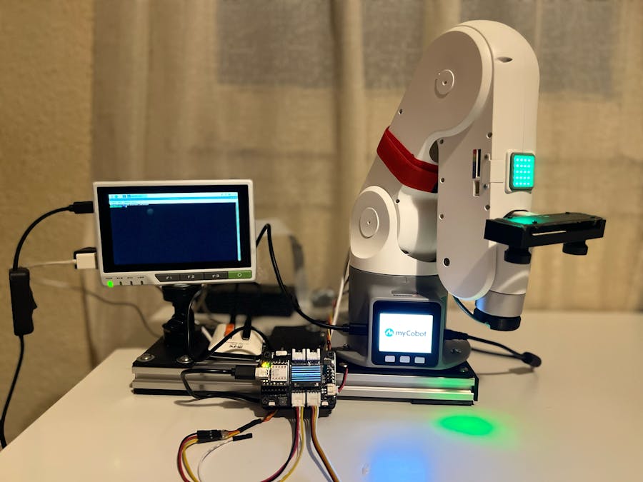
The system presented in this project is a proof of concept in which a robotic arm of the company Elephant Robotics, particularly the myPalletizer arm (Figure 3), was used.
The myPalletizer is an excellent low-cost robotic arm with 4 degrees of freedom, small and easy to program and upgrade with a 3D printer. This makes this robotic arm the right tool for the project presented below.
Aim of the project
The main objective of this project is to create an autonomous or teleoperated robotic system to perform a basic remote medical check-up (Figure 4). This arm would be able to acquire biosignals to validate the robot's functionalities such as:
Photoplethysmography
Photoplethysmography (PPG) is a non-invasive technique that uses a light source and a photodetector at the surface of skin to measure the volumetric variations of blood circulation. Specialists widely use PPG for peripheral monitoring of heart rate and oxygen saturation (SpO2). It has also been used to measure changes in blood pressure mediated by vascular tone.
In general, the heart rate value is measured by the change in blood volume, which is synchronised with the heartbeat, using the signal captured by the photodiode or phototransistor as follow:
1. The LEDs project their light onto the skin and reach the blood circulating in our veins and arteries.
2. The light bounces off the blood in the veins.
3. Finally, the light reflected from the bounce is captured by a photodiode.
The more blood in the blood vessels, the more light is reflected, and vice versa. As the amount of circulating blood, and therefore the amount of reflected light, fluctuates according to our heartbeat, it is possible to know our heart rate with this procedure (Figure 5).
Heart rate sensor was used, as shown in Figure 6.
This is a plug-and-play sensor for Arduino, ESP32, or any other embedded device. It essentially combines a simple optical heart rate sensor with noise cancellation and amplification circuitry, making it quick and easy to get reliable pulse readings. It also draws only 4mA of current at 5V, making it ideal for mobile applications. This sensor was encapsulated in the end-effector arm (Figure 7).In this first version, the different movements have been pre-programmed, in this way, the user will place his arm or chest in a predetermined position, and the arm will capture the signal (Figure 8).PPG signal is obtained using a Seeeduino XIAO (Figure 9), and the data acquired is sent by RS232 to a reTerminal(Figure 10) for its visualisation and analysis.Once the signal is in the reTerminal, it sends it to a database in AWS Dynamo. This would allow specialists to access this data remotely and analyse it, or even use deeplearning models to classify possible pathologies.
In this first version, the different movements have been pre-programmed, in this way, the user will place his arm or chest in a predetermined position, and the arm will capture the signal (Figure 8).
PPG signal is obtained using a Seeeduino XIAO (Figure 9), and the data acquired is sent by RS232 to a reTerminal(Figure 10) for its visualisation and analysis.
Once the signal is in the reTerminal, it sends it to a database in AWS Dynamo. This would allow doctors anywhere in the world to access and analyse this data or use more complex deep learning models to get better diagnoses.
Phonocardiography
Phonocardiography (FGC) is a graphic recording in which the heart sounds obtained with a stethoscope can be observed. Auscultation remains the traditional method and the first primary tool applied for the assessment of the functional state of the heart.
Thanks to the digital stethoscope, we can not only listen to the auscultation sound but also capture, record, measure and graphically represent the auscultation in what we call a phonocardiogram. There is much relevant information in a phonocardiogram, providing data on the timing, relative intensity, frequency, quality, quality, pitch, timbre and precise location of the different components of the heart sound in an objective and repeatable way. Using this information, the specialist can identify and analyse the noises that make up the heart sound; this analysis can be performed separately, and then a synthesis of the different characteristics extracted from the heart sound can be made.
But what exactly is recorded in an FGC? An FGC records the vibration of the heart during a cardiac cycle. This vibration produces an acoustic wave, which propagates through the rib cage. The heart rate is one of the main components of this acoustic wave. However, each heart is unique and has its own mechanical and acoustic characteristics. This means that the acoustic signals of the heart cover a broad spectrum of frequencies, ranging from 1 Hz or less to over 1500 Hz. The amplitude of the acoustic signal is around 80 dB.
When listening to a normal heart, two sounds will be heard: the S1 ("dumb"), which is a broad vibration due to the movement of blood during ventricular systole, the closing of the mitral and tricuspid valves and the subsequent opening of the pulmonary and aortic valves; and the S2 ("tub") which is due to the deceleration and reverse flow of blood in the aorta and pulmonary artery, by the closure of the aorta and pulmonary artery and opening of the tricuspid and mitral valves. This sound is shorter and sharper and coincides with the end of the T wave.
A prototype digital stethoscope has been developed for the robot to perform auscultation of the heart. This stethoscope uses a microphone with an integrated amplifier, as shown in Figure 11.
This microphone is connected to a standard stethoscope; we have cut off the part where the doctor would hear the sounds and added a microphone in this position (Figure 12).
The result is a prototype digital stethoscope based on an XIAO, as shown in Figure 13.
This stethoscope, as well as the PPG sensor, is located on the robot's end-effector (Figure 14).
The robot moves the end-effector to pre-programmed positions, which are determined by the anatomy of the thorax. This is divided into zones on the chest wall from which the different valve sounds of the heart can best be distinguished.
Although the sounds of all valves can be heard from all these areas, the cardiologist distinguishes the sounds of the different valves by process of elimination (Figure 15).
Recording A (Figure 16) is an example of normal heart sounds, showing the vibrations of the first, second, and third heart sounds and even the very weak atrial sound.
Figure 17 shows how the robot takes a phonocardiography signal.
Tele-arm operation
The teleoperation of the arm is vital; this would be used in particular situations; where the robot cannot perform its studies automatically. With the advent of 5G communication and other communication protocols, teleoperation will be used extensively. Although this part of the project, the teleoperation system is only in the simulation phase. It will allow us to see how it can control two myPalletizer arms using the internet as a communication channel.
To carry out this simulation, Pybullet has been used as a 3D and physical constraints tool to control the robot (Figure 18).
In this case, we have two arms; the arm on the left is the arm in charge of the actual component, while the arm on the right is the virtual arm controlled by an operator (doctor).
This teleoperation phase is currently at a fundamental and straightforward stage.
Conclusions
A prototype of a medical robot capable of autonomously capturing two types of bio-signals was realised.
A photoplethysmography capture device based on an XIAO was developed and attached to the myPalletizer robotic arm.
An XIAO-based digital stethoscope was developed and attached to the myPalletizer robotic arm.
The basis for the teleoperation of the arm was laid using a 3D environment such as PyBullet.
Future WorkIn future work, we intend to develop a system for changing diagnostic tools, as the means for this prototype are fixed. At the same time, we are working on integrating a method for measuring blood pressure and electrocardiography. At the same time, we are considering using an arm with more degrees of freedoIn this case, we have two arms; the arm on the left is the arm in charge of the actual component, while the arm on the right is the virtual arm controlled by an operator, in this case, the physician
This teleoperation phase is currently at a fundamental and straightforward stage.
Conclusions
A prototype medical robot has been developed that can autonomously pick up two types of bio-signals.
A photoplethysmography capture device based on an XIAO was developed and attached to the myPalletizer robotic arm.
An XIAO-based digital stethoscope was developed and attached to the myPalletizer robotic arm.
The basis for the teleoperation of the arm was laid using a 3D environment such as PyBullet.
Future Work
In future work, we intend to develop a system for changing diagnostic tools, as the means for this prototype are fixed. At the same time, we are working on integrating a method for measuring blood pressure and electrocardiography. We are also considering using an arm with more degrees of freedom than myCobot, as with 4 degrees of freedom the movements are very limited.m than the myCobot, since, with 4 degrees, the movements are very limited.


Comments
Please log in or sign up to comment.