Having tried out some basic commands on your ARTIK developer board, you'll naturally want to start programming it. In this example, we'll do the IoT universe's equivalent of the famous "Hello World" program – use ARTIK to blink an LED.
We'll begin by doing it manually through the Linux command line, and then compare that to doing it programmatically using:
- Arduino IDE and its library for ARTIK
- Python
- C code.
If you're in a hurry, just try out the Python and C code for now, as they do not require an active network connection.
Otherwise, take a few moments to set up wireless network connectivity. The Arduino IDE requires this, as well as some additional installation. But once you have it all working, you'll quickly come to understand the power and simplicity of the Arduino IDE compared to other methods.
Hardware Required- ARTIK 5 or ARTIK 10 with developer board
- LED
- 220 ohm resistor
- Breadboard and connector wires
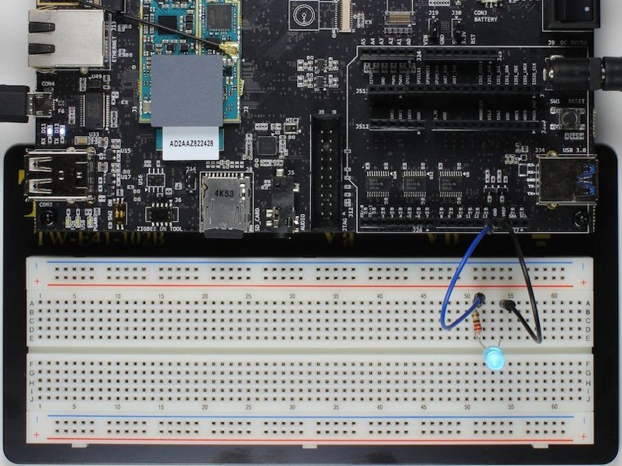
Connect an LED and 220 ohm resistor in series as shown below, between pin 13 (on connector J27) and GND (right next to pin 13). The "active high" output circuitry drives the line in the high (Vcc) direction when programmed to HIGH / 1.
Note about older ARTIK developer boards: Outputs on the older board (with separate debug board) are "active low": a logical HIGH / 1 drives the output low. Because the output can only either drive low or stop driving low, you will need to connect the circuit to 3.3V (on J25) instead of ground, as shown.
Troubleshooting Tip. If you are unsure about how the circuit works, just connect one side to GND and the other to 3.3V on J25 to make sure the LED lights. If it does not, reverse the wires and try again. Note that the LED will not light as brightly when connected to the GPIO pin, whose output drive strength is limited.
The circuit will look something like the picture below (or different if you have an older developer board).
Now that you've built the appropriate circuit, we can set up the GPIO pin.
Blinking the LED ManuallyLinux offers a uniform way to access GPIO pins through its sysfs functionality, which you can read up on here at your leisure. But for now, it's sufficient for you to know that to control a GPIO pin, you first ask Linux to "export" control of it to you, and then write short instructions to its exported control files direction and value.
We're going to start by manually (from the Linux command line) controlling pin 13, which corresponds to sysfs GPIO #22 on ARTIK 10 or GPIO #135 on ARTIK 5. So if working with an ARTIK 5 board, you would proceed as follows.
- Request control of the desired GPIO pin.$
echo 135 > /sys/class/gpio/exportsysfsresponds by creating a GPIO-specific directory (in this case,gpio135).
- Configure the GPIO pin to be an output.$
echo out > /sys/class/gpio/gpio135/directionYou're just writing the string "out" to a file nameddirection.
- Set the output level by writing the
valuefile contents to "1":$echo 1 > /sys/class/gpio/gpio135/valueor "0":$echo 0 > /sys/class/gpio/gpio135/value
The effect this has on the pin depends on whether your board has active-high or active-low outputs. But either way, if you've wired your board up correctly, you should now be able to turn the LED on or off.
Using the Arduino IDEIn order to use the Arduino IDE, you'll first need to set it up on your computer and ARTIK. Follow the "libArduino howto" guide in the Arduino IDE article. (Go ahead, we'll wait.)
The first thing the code does is initialize pin 13 as an output pin with the line:
pinMode(13, OUTPUT);
In the main loop, it switches the LED on and off with the lines:
digitalWrite(13, HIGH);
digitalWrite(13, LOW);
In between the on and the off, you want enough time for a person to see the change, so the delay() commands tell the board to do nothing for 1000 milliseconds (1 sec).
As you can see, Arduino simplifies things by using the pin number directly; you did not need to specify any sysfs GPIO mapping to the pin.
In this version of the example, we configure the pin using Python code.
You can download the code for ARTIK 10 here (for ARTIK 5, change ledpin to 135).
Python is pre-loaded on both ARTIK 5 and ARTIK 10. Execute aspython –i blink.py
C code can be used to control GPIO pins. The example provided here is along the lines of the manual approach shown previously. But normally, C code for this purpose would be within kernel or driver modules, which would not handle it in this way – they would bypass sysfs and act directly on the chip hardware. We'll address that topic once you are more familiar with ARTIK.
You can download the code for ARTIK 10 here (for ARTIK 5, change outputPin


Comments
Please log in or sign up to comment.