

Hardware components | ||||||
| × | 2 | ||||
| × | 1 | ||||
| × | 1 | ||||
| × | 1 | ||||
| × | 1 | ||||
| × | 1 | ||||
| × | 2 | ||||
| × | 1 | ||||
Software apps and online services | ||||||
| ||||||
| ||||||
| ||||||
 |
| |||||
Hand tools and fabrication machines | ||||||
| ||||||
I have taken the components and ideas from earlier prototypes, and want to implement these in a 3D printed housing that will provide a platform for development of an open production model. For a running summary of this work, see: https://www.hackster.io/jim-haseloff/summary-of-airflow-reactor-development-327330
The main fuctional components of the heating and cooling circuits are shown below. These include a 12V 150W PTC heater with integrated 60mm axial fan (red) - mass produced for car heating systems. The heated air from this device is directed into a 3D printed manifold (yellow) that provides a housing for one or more racks of micro tubes. The reactor vessel needs to allow recirculation and re-heating of the closed airflow. In order to cool the samples, two 50mm blower fans are used to drive external air into the system, and at the same time exhaust heated air from the vessel. Temperature monitoring and control of the electrical devices is managed by an Arduino micro controller with user interface through a touchscreen.
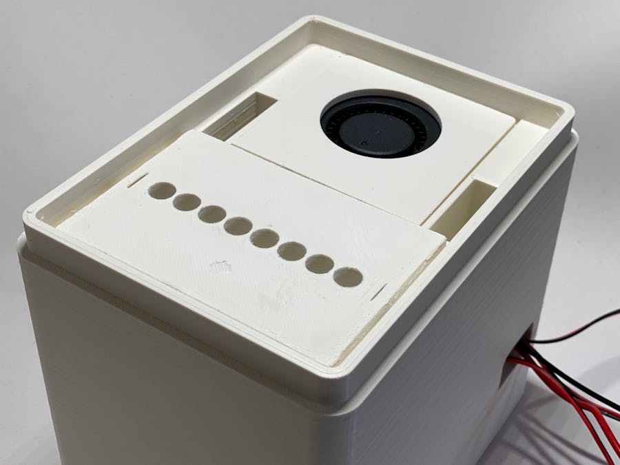
The adoption of airflow manifolds means that the reactor has adopted a taller form, and in order to accommodate this, a box-like 3D printed housing was designed to provide supports for simple assembly of the reactor. The compact box-like form allows relatively simple redesign for different components, if required, and is visually consistent with other scientific instruments, for better or worse. A critical design constraint was to arrange paths for both closed heating and open cooling airflows. In this implementation, the flow of heated air is upwards through the fan heater and manifold. The top surface of the instrument deck (under the lid) is flat, showing the top of the tube manifold and exhaust fan intake (green/black) - and two vents are positioned either side of the exhaust fan that return air to a mixing chamber beneath the fan heater. This allows a simple split path for airflow recirculation during the heating cycle. When cooling is required, both blower fans are turned on, to introduce fresh air into the chamber, and exhaust heated air.
The reactor vessel was printed using Extrudr GreenTEC Pro filament (https://www.extrudr.com/en/products/catalogue/?material=134), which has excellent properties for 3D fused deposition printing and, crucially, is temperature resistant up to at least 115ºC. (Commonly used PLA materials will deform at the temperatures required for DNA denaturation during PCR reactions). I used 2.85mm diameter filament on an Ultimaker S3 printer, with a nozzle temperature of 220ºC, 80% fan. In order to obtain strong adhesion to a heated glass build plate, I used a coating of Magicgoo adhesive, held the plate at 50ºC through printing, and chilled the plate before print removal. (Adhesives like Magicgoo and Dimafix appear to bond more strongly as the build plate temperature increases. One can use plate temperatures up to 90ºC - but this causes difficulty in part removal after printing - see technical documentation at: http://www.dima3d.com/en/home/dimafix/). Higher temperatures result in very strong adherence to the build plate, and was useful for printing large parts without warping of the base and sometimes detachment mid-print.
The main reactor is built from a few components, shown below. I have tried to use custom 3D printed features to allow easy assembly. These are described below.
The electrical parts are cheap. The fan heater cost £12 on Amazon UK, the two blower fans cost £3 each. In addition, the control hardware is based on cheap Arduino components, including MOS-FET switch modules (£2-3 each) and standard 12v DC switching power supply. (see https://www.biomaker.org for information about Arduino systems and the XOD developemnt environment), and https://www.hackster.io/jim-haseloff/programmable-test-rig-part-1-d7df62 for the custom programmable test rig used for prototyping work.
The main vessel is formed from a substantial single 3D print. With 30% 3D cubic infill and 60mm/sec print speed, this print took 2 days, 7 hours to print on an Ultimaker S3. There are likely feasible shortcuts - reducing wall thickness (this design used 9mm thickness for the outside walls), and using a 2D infill pattern - but both would be at the expense of thermal insulation.
The vessel consists of two columns - one is heated, contains the fan heater and manifold. The second column contains the cooling fans and channels for return of heated air to the base of the first column.
In the longer term, assuming a suitably effective design can be found, it would be interesting to explore injection moulding or similar techniques for mass production and cost reduction.
Two cooling fans (lower and upper) are held in custom printed holders, to allow easy installation and mounting in the reactor vessel. The upper cooling fan is positioned to extract heated air from the vessel, and the exhaust is expelled into the surrounding room. The lower fan takes ambient temperature air from the room and injects it into the vessel. A series of intake vents are located in the vessel housing. The fans are both 50mm blower fans (Yotino 7000 rpm, 18 CFM/30, 6 cubic m/hour, 12V. 0.23A; https://www.amazon.co.uk/gp/product/B078SQKJQB £7.99 for 3)
The fans were attached the the printed trays using UV cured glue (Revell FIX-kit). This glue works well with Extrudr GreenTEC Pro materials, and is provided in a tube with a fine metal applicator tube for detailed work. After application of the glue as a viscous liquid, a small torch with longwave UV LED (also provided with the glue) is used to cure the glue - which sets in seconds. The glue is useful for repairs to 3D prints, and for other jobs, like fastening loose items or providing electrical insulation to bare metal surfaces.
The lower cooling fan is fixed to the base of the cooling compartment - a piece of Bu Tack (https://blu-tack.co.uk) works well as a heat resistant "sticky" putty for prototyping purposes, where it is necessary to remove and replace the fan for testing. In the future, I would like to replace the individual carriers with a single slide-in sled that would contain all of the electrical components and wiring, including switching electronics and indicators.
The reactor heating is provided by a PTC heater with fan, usually employed for car interiors. (MAGT fan heater, 12V, 150W; https://www.amazon.co.uk/gp/product/B07X31CBCR/, £12.13). The component is supplied with plastic mounting lugs that need to be removed.
The lugs are formed in the moulded plastic fitting, and can be easily cut away using a fine hacksaw, then filed smooth (as below).
The fan heaters are simply a PTC resistive heating element with casing and spacer attached to a standard dimension 60mm axial fan with self-tapping screws. This allows the prospect of replacing this (relatively low output fan with a higher-powered unit. Examples of possible alternative fans can be found at: https://www.hackster.io/jim-haseloff/microreactor-heating-and-airflow-circuits-part-6-1cc90b. (Section 3: Higher airflows)
The design of the 3D printed reactor housing incorporates brackets to hold the fan heater securely in place. Future designs may incorporate a baffle to minimise the volume of recirculating heated air. Further there are slots provided to allow the rigid leads of the fan heater to protrude into the next compartment, and allow the fan heater to slide neatly into place. In thois version of the design, all leads are taken out of the vessel through a specially placed cable port - for connection to the electronics test rig.
The 50mm blower fan is fixed to the 3D printed tray, similar to the procedure used for the lower fan assembly.
The fan and carrier are placed so that the intake for the blower fan faces the inside of the heated part of the vessel and the exhaust points into the outside room, though a strategically placed venting port.
The carrier for the upper cooling fan forms a flat surface adjacent the two return vents that feed back to the mixing chamber under the fan heater.
The heating manifold is a 3D printed block that slots into the top of the fan heater, it has notches that mate with the side of the vessel, including the channels required to slide in the fan heater unit. In this way, insertion of the manifold block also helps seal the heated part of the vessel.
The manifold is subject to further design efforts - to adapt for even heating of sample tubes, use of different sample formats, inclusion of different detection systems for real-time analysis.
The top surface of the manifold forms a part of the deck of the instrument - and suitable for the creation of a series of drop in alternatives...
Early design for a simple tube support - micro tubes strips mounted directly over the manifold apertures.
The reactor was hooked up to a custom test-rig, and XOD coded programs were used to run it through various temperature cycling regimes.
For example, a record of a mock thermal cycling run is shown below (1 min 95ºC; 1 min 55ºC; 2 min 72º C).
Four traces plotted: heater activity (yellow, lower trace), target temperatures (blue, squared edged trace), sample temperatures (red, green).
Mock PCR experiments with PID controllerPID: P=1, I=0, D=0
PID: P=10, I=0, D=0
PID: P=1, I=0.1, D=0
PID: P=10, I=0.1, D=0
On-Off controller
Temperature cycling was set up to:
1: Heat to 95ºC and hold for 5 min;2: Cool to 40ºC and hold for 5 min;3. Heat to 60ºC and hold for 5 min;3. Repeat.
The temperature control was managed by a PID controller switching between the heater circuit and fan cooling. The PID controller values were set to I=0 and D=0, and the P parameter value were altered. The different plots can be seen below.
During tests of the instrument, a small increase in temperature was noticed when the cooling fans kicked in. It was reasoned that this might be due to strong flow rates driven by the twin blower fans - and that this might contribute to: disturbance of dead air, to be pushed back through the heater and manifold?and/or, reverse air flow, due to built up of pressure in the mixing chamber, and flow up the return channels.
A few adjustments were made to the design of the vessel:
(i) to remove dead space between the fan heater and the vessel walls by adding new horizontal partitions to close amd minimise the size of the mixing chamber located under (and at the entrance of) the fan heater.
(ii) to add baffles to separate the airflows from the two intake sources within the mixing chamber, the return flow and intake vent for ambient temperature air.
(iii) include an extra cable slot for the heater fan leads.
Click on the image below to see more details. The revised .stl file is posted at the bottom of the page.
The Mk II reactor vessel was printed in Extrudr GreenTEC Pro filament (grey) with 230ºC nozzle temperature and glass print bed treated with Magicgoo and kept at 50ºC. The print took 2d 7h, and the plate was cooled to 4ºC for removal of the print.
The working reactor was assembled as described above, and given an initial test by stepping through fixed temperatures of 95ºC, 40ºC and 60ºC and held for 10 minutes each time, after reaching the setpoints. The control was managed using a PID node in XOD, that alternatively switched the heater or cooling fans on or off. The heater fan was kept on to maintaing constant airflow.
The XOD code also included cose for timing, temperature sensing and display. The sketch was loaded into the programmable test-rig (https://www.hackster.io/jim-haseloff/programmable-test-rig-part-1-d7df62), and run with both the Mk I and Mk II reactors.
These two screen shots from the test-rig show a direct comparison between the two vessels. Mk I (above) and Mk II (below). The lower trace (yellow) shows heater activity. The blue trace shows the target temperature, and red and green traces show sample temperatures - on the inner and outer part of the sample rack, respectively.
The Mk II vessel shows a clear improvement in temperature control - with less evident oscillation when the cooling fan was activated. Experiments with the Mk I vessel showed a transient rise in sample temperatures after the cooling fans were activated - presumed due to either flushing of additional heated air from the vessel, or due to altered flow patterns around the air recirculation system. The adjustments made for the Mk II vessel have greatly reduced these.
The sample temperature were also consistently closer - even with the crude manifold used in these experiments. (New manifold designs are being tested, to improve this further).
The only downside was that the heating and cooling times were slightly extended. This may be due to the redesign of the mixing chamber, which could result in higher air pressures, and possible "leakage" of air past the lower fan. (The fan holder is being redesigned to minimise this).
The Mk II vessel was then programmed to run an extended mock PCR cycle, and compared with the performance of its Mk I predecessor. The reaction conditions were: 95ºC 1 min; 55ºC 1 min; 72ºC 2 mins. As seen previously, the Mk I reactor shows oscillations after reaching the set temperatures. These don't appear to be due to the control systems, but more likely due to some instability due to the switched airflow. This is largely absent in the Mk II model. Again, this is at the expense of a small reduction in the speed of temperature cycling.
Overall the Mk II vessel outperforms the first version, and provides some clues for further improvement.
Given the improvements in performance seen by redesigning the mixing chamber for tighter containment of airflows within the vessel, attention turned to the 3D printed holder for the lower cooling fan. The first iteration of the design had a wide opening in the tray adjacent to the exhaust port - and there was the possibility of poor coupling or backflow between the heating and cooling columns in the vessel. Schematic views of both versions of the fan holders can be seen below. The revised fan holder has a closed wall section where it mates with the intake port that leads to the mixing chamber.
The Mk II reactor was tested with both versions of the lower cooling fan holders installed (all other features being kept constant including a test manifold with internal baffle). The instrument versions were run using mock PCR reaction conditions (cycling 95ºC 1 min; 55ºC 1 min; 72ºC 2 min).
There was little apparent difference in performance of the Mk I (above) and Mk II (below) lower fan carriers.
The design of the Mk II lower fan carrier was considered more robust against mis-alignment of the fan or carrier, and so was adopted as a standard component for the Mk II airflow reactor.
Further design tweaks are due: to improve the performance of the airflow manifold - including baffle systems for even sample heating, and introducing heat resistant plastic fibre optic systems for real-time monitoring of reactions.


_t9PF3orMPd.png?auto=compress%2Cformat&w=40&h=40&fit=fillmax&bg=fff&dpr=2)


Comments