


Hardware components | ||||||
| × | 1 | ||||
Software apps and online services | ||||||
| ||||||
| ||||||
Hand tools and fabrication machines | ||||||
| ||||||
Previous microreactor prototypes showed the promise of using fan heater components for cycling temperature control. Car fan heaters are low cost, and contain 12V, 100W PTC elements which allow rapid air heating, which can be directed and switched using simple fans. The elements have a high heating capacity in small reactor volumes, and manifolds were designed to harness heated airflows, to minimise temperature differences across multi-tube samples, and maximise heating/cooling rates.
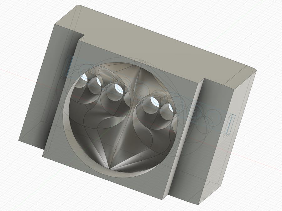
The manifold was printed as a block, with slots that allowed it to plug into a position above the fan heater. The heater was positioned to blow air directly into the manifold block - and the 50mm diameter circular outlet was evenly split and directed across the surface of each of the 8 microtubes of a mounted strip. Heated air passed to the top of the chamber, where it could be recycled back to the entry of the heater via a side channel. The manifold was 3D printed with a channel for insertion of a DS18b20 temperature probe, to allow monitoring of heating and air mixing. Two blower fans are mounted to provide controlled inlet and exhaust of air, and which allow Arduino-controlled regulation of air heating and cooling. In order to accommodate the taller manifold block - a 60mm tall lid was printed to fit.
The assembled reactor was hooked up to an Arduino-based custom programmable test rig with touchscreen - described at: https://www.hackster.io/jim-haseloff/programmable-test-rig-d7df62. This allowed the control of the heater, fans and temperature sensors through a graphical interface programmed in XOD (https://xod.io). XOD allows code-free prototyping of control interfaces and display through programming a series of software nodes, followed by download to the test-rig. The image below shows a sketch contianing a prototype control system that aims to:
(i) Initialisation of the device and communication between the Arduino and touchscreen at 38, 400 baud, and trigger thermal cycling after the start button on the touchscreen is pressed.
(ii) In this prototpye, cycling was set to:1. Heat to 95ºC and maintain for 1 min2. Cool to 55ºC and maintain for 1 min3. Heat to 72ºC and maintain for 2 min...then repeat(These are typical values used for polymerase chain reactions)
(iii) Three temperature sensors are embedded in the reactor. These are wired DS19B20 devices (construction described at https://www.hackster.io/jim-haseloff/programmable-test-rig-d7df62). One sensor was located in the body of the airflow manifold, and attached to port D7. Two other sensors were placed in outer and inner sample tubes, to more accurately measure temperature effects for future samples.
(iv) Independent software clocks were used to controls the rates of reading data and writing to the touchscreen. Intervals of 1 sec, 100 msec and 5 sec were used to control timer readout, temperature reading and control, and screen plotting, respectively.
A view of the entire program or "sketch" is shown below.
A central software block is devoted to reading the current temparature in the reactor, comparing this with the current "target" temperature and either maintaining power to the 60mm fan heater (in heating mode), or switching off the heater and turning on the two 50mm blower fans to cool the device with flow of ambient temperature air.
Progress through the temperature cycling is implemented via a simple state machine that cycle through three phases of melt (95ºC), anneal (55ºC) and extend (72ºC) - these are arbitrary and can be altered anywhere between ambient and 100ºC with the current prototype components and materials. In the sketch fragment shown below, a triggering pulse is used to enter the melt phase. On completion, a pulse is sent to the select node, to change the target temperature from the default 95ºC to 55ºC, and activate the anneal phase. When the anneal phase is complete, it passes a pulse to select the next target temperature (72ºC) and pass control to the extend phase. When this is complete, it resets the melting temperature and melt phase...and so on.
Behaviour in the different phases is set within three custom nodes which take three inputs, activation pulse, current and target temperatures - checks whether the current temperature is higher or lower than the target - and generates a pulse if the appropriate state is true. (This acts as a delay until the reactor has heated or cooled to the next target temperature). The "true" pulse is then combined with the original activation pulse in a wait-all-once node, to trigger a delay node. The delay node is set to a time value that corresponds to the required duration of the phase. When the delay is finished, it feeds a pulse to the output - to mark completion of the phase, and internally resets the wait-all-once node.
The internal workings of the phase nodes are shown below. A simple guide to programming similar sequences in XOD can be found at: https://xod.io/docs/guide/simple-traffic-light/. Programming control sequences in a dataflow programming environment like XOD is different to "normal" control flow languages, and the guide can be useful.
In this simple prototype, the software was set up to start cycling through the different temperature phases after pressing the start button, and to plot the readings of the different sensors over time (one reading per 5 sec). Plots were obtained for three temperature sensors and one trace was used to indicate when the heater was powered up.
4. 3D printed prototypeThe prototype was printed in GreenTEC Pro biopolymer filament, which is heat resistant, tolerating temperatures over 115ºC before deformation. The material is also easy to print, similar to PLA, albeit with higher print nozzle temperatures (210-230ºC). The 3D printed components correspond to vessel base, lower intake fan carrier, upper exhaust fan carrier, airflow manifold with integrated tube holder and 60mm (taller) lid to accommodate the new manifold. STL files are provided below. The components were designed in Autodesk Fusion 360, based on same or similar componenets described in an earlier prototype (https://www.hackster.io/jim-haseloff/thermal-cycling-airflow-reactor-i-6c72cd).
The electrical components were mounted within the reactor and wired to the test rig. The images below show the manifold mounted on the vessel base, and sensors and fans connected to the control electronics. All fans were switched using off-the-shelf MOS-FET electronic modules. Where it was necessary to run leads into closed heating compartment of the reactor, holes were drilled and plugged with Blu Tack - works well up to 100ºC.
Photo of the test rig screen that shows about an hour of thermal cycling. The red trace shows the temperature reading at the periphery of the airflow manifold, which lags the temperature changes seen at the sample tubes (blue and white traces) - which are close in value. The yellow trace shows the regulated activity of the heater.
In this prototype, the output of the fan heater is directed upwards into the circular entry port of the airflow manifold - then distributed to each of the eight tubes placed at the manifold outlets. While heating is driven by the 150W 12V PTC resistive heating element, cooling is initiated by (i) switching off the heater element (the associated fan stays on to maintain air circulation past the sample tubes), and (ii) activating both the intake and exhaust blower fans, which are positioned outside the heating chamber, and which introduce ambient temperature air into the chamber. The 50mm blower fans produce a high rate of airflow from outside the chamber - but the chamber and heater retain heat, and the result is a useful and easy to regulate shift in temperature. In this prototype, I am using a XOD PID controller (see XOD sketch above), but this has not been tuned (awaiting final layout of the heating/cooling circuit) - so room for improvement.
The speed of heating and cooling is quite acceptable, compared to laboratory instruments used for routine PCR experiments - a 4 minute cycle (95ºC for 1 min; 55ºC for 1 min; 72ºC for 2 min) took about 7 min per cycle - and the cost is difficult to beat - about £40 of print filament, heater and fans, not including a DIY Arduino controller with customisable touchscreen.
The software needed improvement and debugging - occasional control pulses appeared to go missing or were misinterpreted during cycling, and the control software is very bare-bones! This was fixed by insulating the state nodes by adding triggered gates - as shown in the sketches above (thanks to Matt Wayland for helpful hints about this). An example of a run with the fixed code is shown below.
There are a number of planned improvements for the control software - including a user interface for easily choosing protocols and changing settings/
The geometry of the airflow manifold should be optimised, this prototype is a crude design, based on rules of thumb for splitting the air flow into eight more-or-less equal branches. The mounting of sample tubes requires some attention.
The overall design of the reactor can be adjusted to take into account the use of the relatively bulky manifold - to minimise the volume of airflow and build a more compact design.


_t9PF3orMPd.png?auto=compress%2Cformat&w=40&h=40&fit=fillmax&bg=fff&dpr=2)


Comments
Please log in or sign up to comment.