In the recent years, a lot of new low power sensors have emerged. Time of Flight (ToF) sensors are becoming very popular in embedded solutions because they are cheap and can be used in a lot of situations, not only for measuring distance, but also for presence detection or human interaction. The VL53L5CX multizone ToF sensor, which is used in this project, being capable of capturing a matrix of 8x8 different distances at once, is a unique device which has a lot of possibilities in gesture detection by its own, as the manufacturer shows, but can also provide extra information for other sensors based in image capture like the camera board from the Sony Spresense Development kit.
Combining the distance information with image recognition could improve classification results in embedded machine learning solutions, but lots of data are needed for training this kind of models which could be then implemented on a board like the Sony Spresense (for example, via Edge Impulse platform, which is fully compatible with the used hardware).
This project is a first step into these machine learning based applications by providing a hardware platform with the necessary tools to log all image and distance data very quickly, directly from the device itself, with no need of a PC for the recording process. This way, the dataset creation step is done in just minutes, and recorded to a flash memory.
Although the project has achieved this objective, more improvements need to be made for this device so the records are accurate, which haven't been done due to limited time: calibrating the sensors for perfect matching image and distance, for example, has proven to be mandatory after checking the test data. This would require them to be permanently fixed to a case or custom PCB. This improvement and others are discussed at the end of this document, hoping that future iterations of this device could cover all of them.
Parts information- All the programmable devices and sensors used are part of the Sony Spresense Development Kit (except for the VL53L5CX ToF multizone sensor, which is a part from the manufacturer ST). The Sony Spresense hardware has been provided for free via Hackster.io.
- The VL53L5CX ToF multizone sensor can be found in the form of a evaluation board which is sold directly by the manufacturer, ST, with the name VL53L5CX-SATEL. This reference comes with 2 identical boards in one package. This will be the one used in this project, but note that you can find this same sensor at another two development boards from SparkFun. This project is fully compatible with these boards. In fact, SparkFun's VL53L5CX libraries for Arduino are the ones used here. A custom board with this same sensor could be also compatible as well.
- Other tools necessary for the project are a micro SD card (data is not very big, so almost any size will do for pretty large datasets), a micro-USB cable, and at least 10 male-female jumper wires.
- Finally, something which isn't mandatory but is totally recomended is a larger flat cable for the board module, since the one included is pretty short and allows little manipulation of the camera board position. Wurth Elektronik WR-FFC Flat Flexible Cable (reference 687620200002) goes up to 200mm and makes it easier to put the camera in desired position. Please note that Sony recommends using the shortest possible cable for a better functioning of the camera board. This longer cable has been tested successfully with different camera examples, so it should be OK.
1. Install Arduino IDE
Latest version should be available at https://www.arduino.cc/en/Main/Software. Download the file matching your OS and install it.
2. Install Spresense board package
At the manufacturer website you can find a tutorial with all the necessary steps for using the Spresense board with Arduino IDE: https://developer.sony.com/develop/spresense/docs/arduino_set_up_en.html
Testing the correct functioning of the board before proceeding the next steps is strongly recommended. With the installed libraries you will find lots of different examples to try.
3. Install SparkFun's VL53L5CX library
This can be done directly from Arduino IDE's Library Manager. You can access to this menu from Sketch/Include Library/Manage Libraries... or by pressing Ctrl+Shift+i. This library is also available for manual installation at https://github.com/sparkfun/SparkFun_VL53L5CX_Arduino_Library
Step 2: Hardware connection
1.Spresense setup: You can follow the steps at the manufacturer guide to connect the main board to the extension board, and then the camera board to the main board: https://developer.sony.com/develop/spresense/docs/introduction_en.html
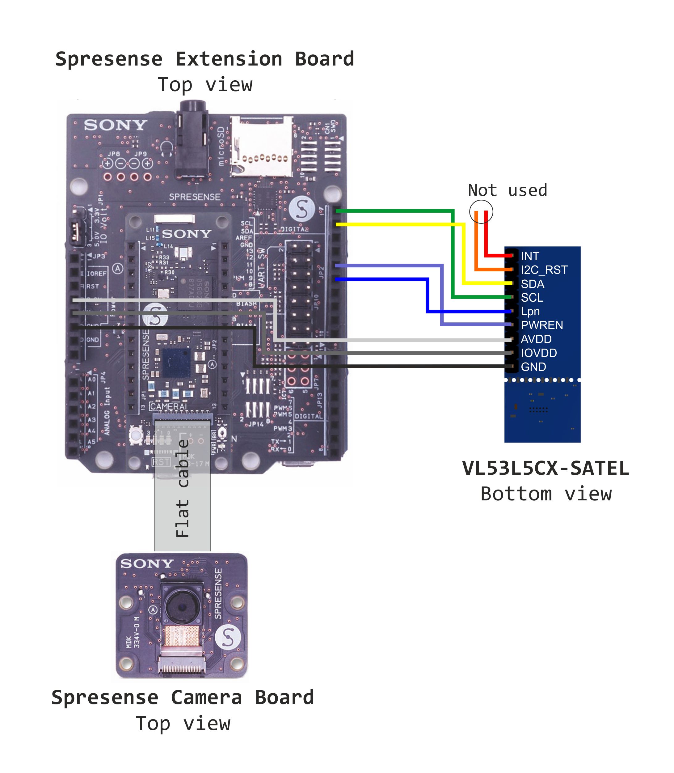
2.Connecting the VL53L5CX-SATEL board: You can simply follow the provided schematic to connect the pins using male to female jumper wires, but it is recommended to review the following guides to understand what each pin does and how to use them:
- How to setup and run the VL53L5CX-SATEL using an STM32 Nucleo64 board (ST's application note AN5717).
- SparkFun's tutorial Qwiic ToF Imager - VL53L5CX Hookup Guide (for SparkFun's board, but they uses almost the same signals that the ST's VL53L5CX-SATEL boards).
At the repository found at https://github.com/juamonsan/Spresense-Camera-ToF you will find all the code related to this project. There is a simpler version which only uses the VL53L5CX ToF sensor (in case someone doesn't have or doesn´t need the camera) and the full version which uses both camera and ToF sensors for the captures. The latter is the code that will be described onwards, but the two are very similar.
Simply clone the repository or download it as a.zip file and then open the.ino desired file with Arduino IDE. Compile it and upload it into the board.
All the code is based in examples provided at the libraries by Sony or SparkFun for their respective boards. Mostly camera, SDHC and VL53L5CX examples.
There are some parameters you can change at the code like the amount of captures taken or the time between one capture and the next one. By default, only 10 captures are stored at the SD, and then the program ends, leaving the ToF sensor disabled by lowering the Power Enable pin.
Image resolution can also be improved at the camera setup function, but if this is done then you probably must increase the allocated memory at the board from the tools menu of the Arduino IDE. By default, the resolution is VGA in JPG format.
All the steps the program does are described through serial port for debugging and monitoring, so opening the Arduino IDE's serial monitor is strongly recommended for troubleshooting.
Step 4: Data captureAt boot, the board will do all the preliminary setup steps and then will start to take pictures with the camera board and ToF lectures with the ToF sensor, storing them at the SD card. After one capture, there is a configurable wait time where a LED animation is shown, and then the next capture is taken, until reaching the desired quantity (10 by default).
Please note that, by default, the new data overwrites the old at the SD card, so after each logging session you must remember to save the data somewhere else if you don't want to loose it. This could be improved in the future by creating a new folder each time the board boots, but this is yet to be done.
The sensors need to have the same orientation, so please refer to the picture provided. No case or proper fixing device has been designed yet, thus this will be ideally the best solution. In any case, both sensors need to be as close as possible to minimize the offset error.
This step is not necessary for dataset creation, and it is only done for visual representation of the data.
Using Matlab, a little script has been made to merge in one 3D figure both the camera image and the ranging sensor distances measured.
To use it, simply change the workspace to the script folder and run it. You can process one lecture at a time. Change the relative directory to other folder or file to see different results from the test data, or change it to a file of your own.
All test data captured until now, which is also provided as an example at the repository, is not very accurate. This is due to a lack of calibration and a very provisional setup of the sensor boards, which is OK for testing the device but not enough for real lectures. Since the sensors have different field of views and ranging, a further calibration and study needs to be done yet.
After performing this calibration study, and determining if this should be done either by an accurate fixed position of the sensors or either by latter software processing, a 3D printed case, a custom PCB including sensor positioning, or even both, are planned. The device could even be fully autonomous by using a battery as the power supply.
Other possible improvements include:
- Creating alternative code to send the readings via serial and a custom desktop app to allow two ways communication.
- Implementing video recording.
- Creating a new folder each time the board boots to eliminate the need to overwrite old data from the SD.
- Including more than one ToF matrix sensor to cover more area.
Future works will of course include modelling a machine learning algorithm with the datasets created to recognize hand gestures and shapes, embedding it on the Spresense board, and comparing the results between camera only and camera+ToF setups to see how can this improve the accuracy of the classification process.
Thank you for reading and please let me know in the comments whatever mistake or improve suggestion you have encountered while reading or reproducing this work.


Comments
Please log in or sign up to comment.