This project came about after playing with a rotary encoder and wondering how it could become the basis for a rotary combination lock.
I started out with a knob with numbers like the rotary combination lock on a safe. What I found was that no matter how much the rotary encoder contacts were debounced, very slow or very fast rotations would cause the code to lose synchronization with the numbers on the dial. I tried various 20 step and 24 step encoders and they all got out of synchronization with the code. I was about to order some absolute encoders when I thought that rather than number the dial, I could display what the code thinks the dial is currently set to on a small OLED screen. This meant that synchronization was no longer an issue. It also meant that the number steps were not restricted to the maximum number on the dial.
The next step was to figure out the code. Simply put, a combination is a number of steps after zero, followed by a number of steps before zero, followed by a number of steps after zero, followed by a number of steps before zero and finally the dial being rotated back to zero. At which time a button is pressed and the combination is compared to the sequence stored in EEPROM.
Once this was working, the next step was to figure out a practical use for it. I remember seeing a Password Pump by Daniel J. Murphy. It seemed like the ideal project.
Since the size of this unit makes the dongle emulating a USB Keyboard approach impracticable, this unit emulates a Bluetooth keyboard instead. By using a ESP32 module that not only incorporates Bluetooth but also Wi-Fi meant that configuration of the username/password table can be done using a standard Internet browser.
Demonstration of final unitFeatures- 4 digit rotary dial combination lock
- Master 4 digit code with salt one-way encrypted with SHA-256
- Master password and unique salt for each credential are stored in EEPROM
- Credential table stored in SPIFFS (Flash memory emulating a Flash drive). The table is currently coded for a maximum of 20 entries. However this can be extended if you wish.
- Username & password symmetrically encrypted with AES-128 with salts
- Web server to allow changing of master password and add/modify/delete password table via a browser.
- Bluetooth keyboard emulation to send the credentials to an Application or a Website.
Note: ESP32 doesn't really support both Wi-Fi & Bluetooth at the same time. Power down after updating the password table over Wi-Fi before sending credentials via Bluetooth.
The Browser InterfaceAfter entering the master combination, you will be presented with the menu. One of the menu options is "Edit locker". Rotate the dial until it appears and press the button to connect to the Internet over Wi-Fi. Once it is connected, the display shows the IP address to use to access the credential table. Type this into your browser's address bar prefixing it with "http://". eg "http://192.168.0.21"
1. Check the "Change Master Password" checkbox.
2. Enter the old password in the form "-n+n-n+n" or "+n-n+n-n" where n is a number between 1 and 99. The plus and minus symbols determine the direction of the dial (+ is right, - is left). The only requirement is that the symbols alternate between the four numbers. By default the master password is "+1-2+3-4".
3. Enter the new password following the same rules as described above.
4. Click the "Save Changes" button.
If there aren't any errors, the message "Master password changed" is displayed.
Adding a username and passwordEnter a display name to appear on the OLED screen. It cannot exceed 14 characters.
Optionally enter the username if the site you will be sending the credentials to requires one. From the drop-down list directly to the right of the username field, select whether a Tab, CR (Enter key) or nothing should be sent after the username is transmitted.
Optionally enter the password if the site you will be sending the credentials to requires one. From the drop-down list directly to the right of the password field, select whether a Tab, CR (Enter key) or nothing should be sent after the password is transmitted.
Click the "Save Changes" button.
Deleting a entryClick the blue trash icon to the left of the entry you wish to clear.
Confirm that you wish to proceed
Click the "Save Changes" button.
How to connect using Windows 101. Power on the Combination Password Locker
2. Right Click on the Windows icon (Bottom left corner on screen) and select Settings.
3. Click on Devices (image step 1)
4. Click " + Add Bluetooth or other device" (image step 2)
5. Click the Bluetooth option (image step 3)
6. Click "Password Locker" (image step 4)
7. The "Password Locker" should appear under "Mouse, keyboard, & pen" and show "Connected" underneath it (image step 5)
After entering the master combination, you will be presented with the menu.
Rotate the rotary encoder until the display name that represents the credentials appears.
Ensure the Application or Website that you want to log into is open on your PC. Click in the username field so it gets the focus.
Press the button on the Password Locker to send the credentials. Because the Password Locker is now acting as a keyboard, the Application or Website will assume you typed it in via your keyboard.
3D printingThe printing of "Knob.stl" requires a filament change at 101 and 103 when printing with a 0.2mm layer height and with supports touching the build plate. Start with black filament, switch to white at the start of layer 101 and switch back to black at the start of layer 103.
All other printing is done using a 0.2mm layer height with no supports. The top, front, text and back pieces will need rotating on the built plate before slicing.
After printing "RotaryMarker.stl", glue a short piece of 1.75mm white filament in the slot provided.
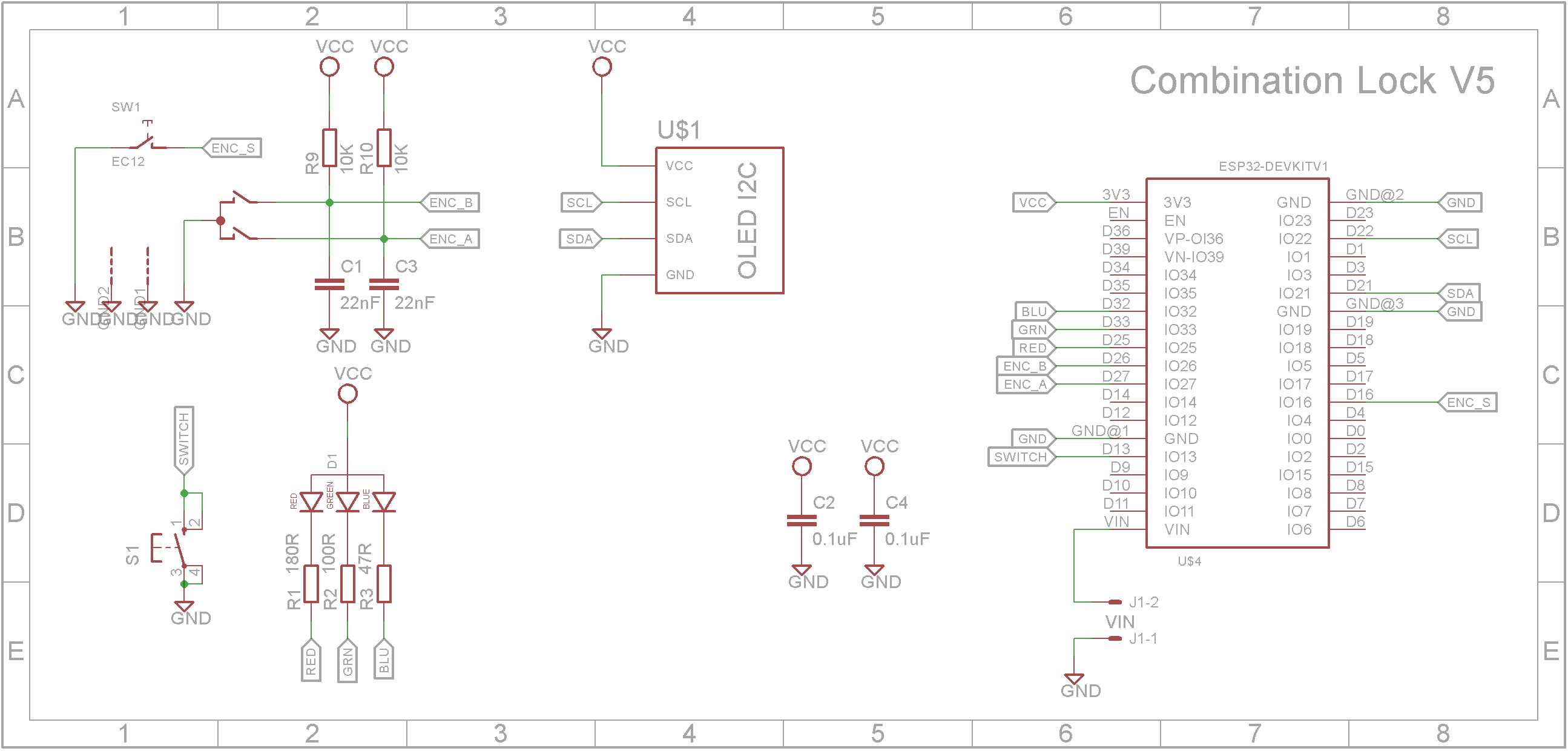
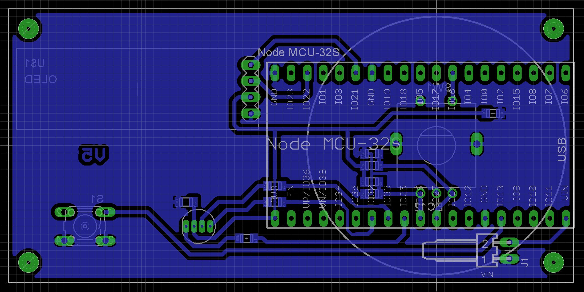
SchematicThe were a number of variants built before this final circuit design. The build that is shown in the assembly images is that of V3. It contained a 24C512 external EEPROM and a TP4056 charging module. Both these parts were not used and are removed from the V5 circuit.
Note: some of the images are from by V3 build which included a 24C512 EEPROM, 4 pin connector for a PS2 keyboard and a TP4056 charging module. The assembly process regardless of version remains the same.
I have included the Eagle files in case you want to get the board commercially made or do as I did and make it yourself. I used the Toner method.
Start by adding the SMD components
Add the top-side components
3D print "Spacers.stl" and glue them on the board as shown.
Using a 4 pin female Dupont header with long pins, connect it to the OLED screen and solder the connector to the copper side of the PCB.
Mount the common anode RGB LED to the PCB. The spacer will give it the correct height.
Add the rotary encoder and switch.
Glue some 1.75mm white filament into the slot on "RotaryMarker.stl". Then glue the assembly to front panel making sure the white filament is at the top.
Sit "Button.stl" in its hole on the front panel.
Screw the board to the 4 pillars using 6mm M3 screws. Make sure the button shaft seats correctly in the hole on "Button.stl".
Add the knob onto the rotary encoder shaft.
One of the many issues I found during this build is that the Bluetooth part on the ESP32 cannot run on 3.7V. It kept resetting the ESP32. To solve this I took the TP4056 charger unit off the board and mounted a 5V booster with Lithium-Ion battery charger on the back of the case.
Add a 18650 battery holder, switch, DC panel socket and the Lithium Battery Boost Module 2A 5V Out, 3.7-4.2V to the back of the case.
Upload the attached software to the ESP32 Development module. The two settings in the Arduino IDE Tools menu are:
Board: "Node32s"
Partition Scheme: "No OTA (Large APP)"
Before you upload the code to the ESP32 Development kit, modify lines 18 and 19 in "Webserver.h" by adding your SSID and password to your Wi-Fi router. Also change line 7 in "Hardware.h" to read "#define V4"
The lugs on the clam shell can sometimes split on a 3D printed layer line when the screw is inserted. To protect against this, super glue a nylon washer to each lug.
Finally screw the case together using four 6mm M3 screws.
Now you won't have an excuse to use hard to remember random long unique passwords on all your websites and applications.
As for a future enhancement, the Web interface needs some TLC. It needs to be a fluid design so it can adapt to phones, tablets and desktop browsers. Also the selection of a maximum of 20 credentials was based on not wanting the page to scroll in the browser. A future implementation could use a virtual list or a paging system to allow the easy editing of hundreds of entries.
All in all, it was a challenging build with many issues that had to be overcome. Thankfully perseverance won out in the end. 😃


Comments
Please log in or sign up to comment.