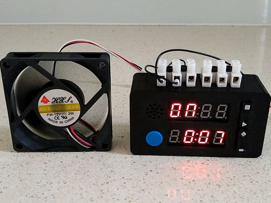
Over the years I have build many timers and of course many Apps abound for your mobile phone. But when I really wanted one to simply automatically switch on and off a circuit that I was working on, none of them fitted the bill. So I built this relay timer.
DemonstrationOperationThe timer is controlled by 5 buttons
In Menu mode (timer not running), the Stop & Start buttons step through the following configurable items:
- Off format - Displayed as "OF F" - Determines whether the OFF time shown is in hours and minutes or in minutes and seconds. Use the Up/Down buttons to switch between two options. Either "HHnn" or "nnSS".
- Off time (left two digits flashing) - Displayed as "OF t" - Represents the OFF time hours or minutes depending on the OFF format selected. Use the Up/Down buttons to set the left two digits.
- Off time (right two digits flashing) - Displayed as "OF t" - Represents the OFF time minutes or seconds depending on the OFF format selected. Use the Up/Down buttons to set the right two digits.
- On format - Displayed as "ON F" - Determines whether the ON time shown is in hours and minutes or in minutes and seconds. Use the Up/Down buttons to switch between two options. Either "HHnn" or "nnSS".
- On time (left two digits flashing) - Displayed as "ON t" - Represents the ON time hours or minutes depending on the ON format selected. Use the Up/Down buttons to set the left two digits.
- On time (right two digits flashing) - Displayed as "ON t" - Represents the ON time minutes or seconds depending on the ON format selected. Use the Up/Down buttons to set the right two digits.
- Loop - Displayed as "LOOP" - Determines when started whether the sequence is played once or is repeated continuously. Use the Up/Down buttons to switch between two options. Either "ON" or "OFF".
When in Menu mode and the menu shows "PLAY", pressing the Play button will start the timer. If you haven't set a OFF time or ON time, the bottom line will show "Err" and returns to Menu mode. Should either the OFF time or ON time or both be set, the timer will start. The buttons have the following functions:
- Stop button - Pauses the countdown.
- Start button - Continues the countdown when paused
- Play button - Aborts the countdown and returns to Menu mode when paused. Also the relay will be switched off.
Should looping be off, at the end of the sequence, the system will automatically go into pause mode and show "dONE" on the top display. Also the relay will be switched off.
3D printingThe STL files required for 3D printing are included. You can either print them yourself if you have access to a 3D printed or take them to a commercial 3D print shop.
The recommend Slicer settings are as follows:
"Case - Bottom.stl" - 0.2 layer height, no supports
"Case - Front.stl" - 0.2 layer height, no supports
"Button_Tops.stl" - 0.1 layer height, no supports, switch to contrasting color at start of layer 54
"Spacers.stl" - 0.1 layer height, no supports
Drill out the four PCB mounts using a 2.5mm drill and create a thread using a 3mm tap.
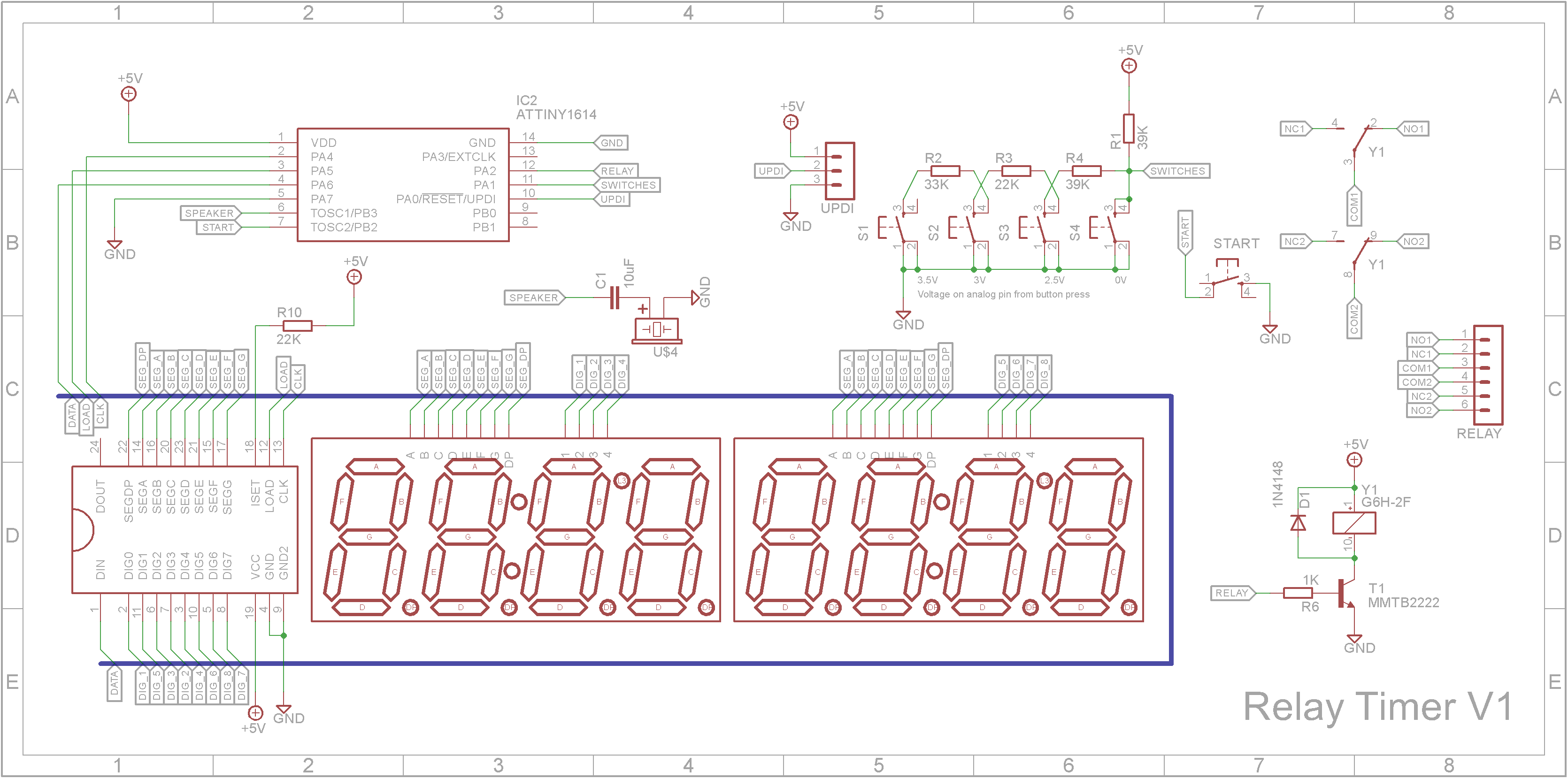
SchematicThe timer uses a ATtiny1614 microprocessor along with a MAX7219 8 digit LED driver IC. The Start/Stop/Up/Down buttons are connected to a voltage divider so that can share a single analog pin on the microprocessor. The DPDT relay is a Omron G6H-2F that came from a Rocky Electronics sale. The displays are 0.4in 4-Digit 7-Segment Clock displays that came from Ali-Express.
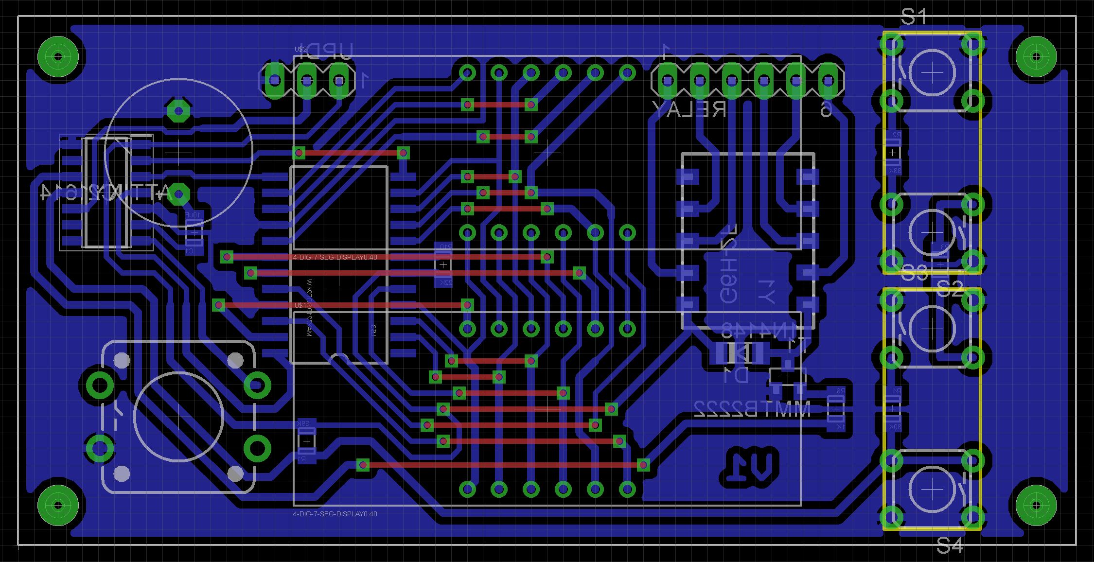
The PCB was designed for parts I already had around the workshop. The board contains a mixture of through hole components and Surface Mount Devices (SMD).
The Eagle files have been included should you wish to have the board commercially made or you can do as I did and make it yourself. I used the Toner method.
Start by adding the SMD components. I find it easier to use solder paste rather than use solder from a reel when soldering SMD components. I used my SMD Reflow Hot Plate to reflow the solder paste under the SMD components.
Add the links if your board is single-sided.
Add a 3 pin straight male header to the copper side of the board. This header is used to program the ATtiny1614 and also doubles as the power connector. Dab some red paint on the +5V pin so you don't accidently plug the battery connector in the wrong way.
Add a straight 6 pin male header to the copper side of the board. This is where the wires to the terminal blocks plug in.
On the component side add the two 7-segment displays, four 6x6mm tactile switches with 8mm shafts, a 12x12mm tactile switch with a round button top and the passive buzzer.
When adding the 7-segment displays add the spacers you 3D printed under the displays so they sit at the correct height before you solder them in place.
Place the Stop/Start and Up/Down button tops into their respective holes and fix the PCB to the from of the case using four 6mm M3 screws. Make sure the buttons work. You may need to unscrew the PCB and file away any obstacles stopping the switches from operating correctly.
Solder right-angle male pin headers to the straight male pin headers you added in Step 2 otherwise the Dupont female connectors won't clear the battery and charger board.
According to the MAX7219 datasheet, its minimum supply voltage is 4.5V. As this build uses a single 3.7V Li-Po battery, I used a charger with a boost circuit on it. You can get these modules from Ali-Express. Search for "USB 18650 Lithium Li-ion Battery Charger Module Boost 3.7V to 5V 9V 12V Adjustable DC-DC Step Up Boost Module". They are around $1 each.
After adding the battery wires and supply wires to the charger/boost module, use hot glue to fix the module to the base.
Two 3 way screw terminal connectors are screwed onto the outside of the case and connected via wire holes to the the relay outputs. You need to drill holes in the case to fit the terminal blocks that you use.
Unlike the earlier ATtiny series such as the ATtiny85, the ATtiny1614 uses the RESET pin to program the CPU. To program it you need a UPDI programmer. I made one using a Arduino Nano. You can find complete build instructions at Create Your Own UPDI Programmer. It also contains the instructions for adding the megaTinyCore boards to your IDE.
Once the board has been installed in the IDE, select it from the Tools menu.
Select the ATtiny1614 board in your IDE
Select Board, chip, clock speed, COM port the Arduino Nano is connected and the programmer
The Programmer needs to be set to jtag2updi (megaTinyCore).
Open the sketch and upload it to the ATtiny1614.
ConclusionIt maybe a bit of an ugly duckling in the looks department but it performs its duty admirably. 🦆👍


Comments
Please log in or sign up to comment.