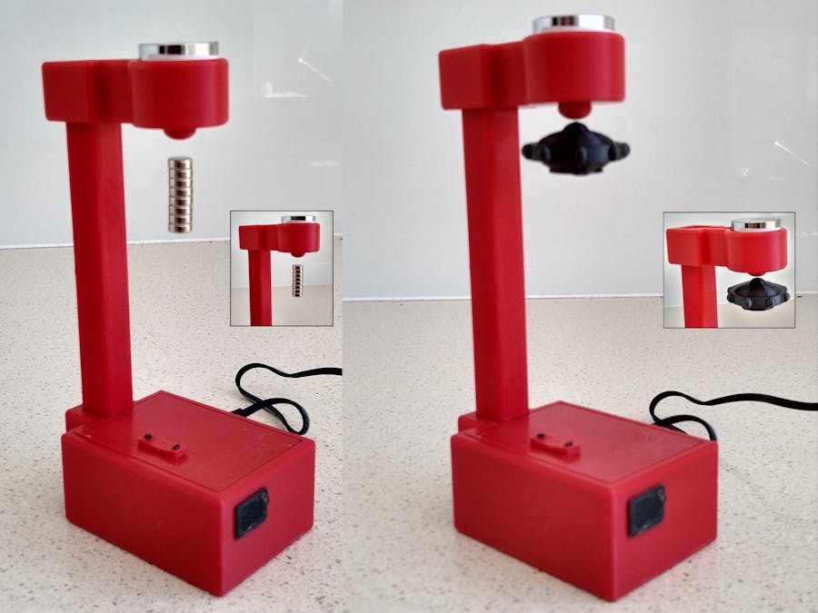
This is my build of Magnet Levitation with Arduino by fellow Hackster jsirgado. This version differs in the following ways:
- Replaced Arduino Nano with ATtiny1614 microprocessor
- Added a 3D printed rocker switch to adjust the levitation point
- Created a replacement "base_cover.stl" that incorporates the 3D printed rocker switch and PCB support pillars.
- Modified the "ufo.stl" to support two 15mm x 4mm round magnets
The circuit is based around a ATtiny1614 microprocessor and a AO4406 N-Channel MOSFET driving a 12V Solenoid.
An OH49E linear hall effect sensor detects the distance of the levitating magnet and switches the solenoid on and off to maintain the levitating magnet at a fixed height. The software has two modes:
The first is a simple switching on or off the solenoid around the levitation level. This method can cause instability due to its "all or nothing" approach to switching on and off the solenoid.
The second uses a PID algorithm and PWM to maintain the levitating magnet at the correct height. This method removed the instability of the first method but determining the PID values can be difficult.
3D Printing"new_base_cover.stl" - 0.2mm layer height, no supports
"new_ufo.stl" - 0.2mm layer height, supports touching build plate
"rocker_switch.stl" - 0.1mm layer height, no supports, change to contrasting color at the start of layer 54.
"base_plug.stl" - 0.1mm layer height, no supports
The other files are printed with a 0.2mm layer height and no supports.
PCBThe PCB uses SMD components due to the fact that the ATtiny1614 only comes in a SMD form factor.
The Eagle files have been included should you wish to have the board commercially made or you can do as I did and make it yourself. I used the Toner method.
Assembly - Step 1Start by adding the SMD components. I find it easier to use solder paste rather than use solder from a reel when soldering SMD components. I also used my SMD reflow hot plate that I built a few months back to reflow the solder paste.
Add the links if your board is single-sided.
Add the 3 pin right angle male header for the leads that come in from the OH49E sensor onto the copper side of the board.
Add the 2 pin right angle male header for the leads that come in from the solenoid onto the copper side of the board.
Add the 3 pin right angle male header for programming the ATtiny1614 using a UPDI programmer.
Add the 2 pin right angle male KF2510 pin header for the 12V power input.
Add the two 6x6mm tactile switches with 8mm shafts to the comnponent side odf the board. Don't solder them to the board yet.
Insert the 3D printed "rocker_switch.stl" into the hole on the base cover.
Screw the board to the base cover using four 6mm M3 screws.
Ensure the rocker switch works correctly before finally soldering the two tactile switches.
Program the ATtiny1614 using a UPDI programmer (See programming section)
The assembly of the arm and magnet is the same as the jsirgado's version. See Magnet Levitation with Arduino. Ensure you wire the OH49E hall sensor correctly and it is orientated correctly.
Run the wires down the inside of the pillar add fit the female Dupont headers to the ends.
Assembly - Step 5Drill out the hole on the side of the base using a 7mm drill. Elongate with a rasp so that the DC panel socket fits into the hole.
3D print "base_plug.stl" and place it in the hole that was originally designed for the Arduino Nano USB socket.
Plug in the connections and close the case.
The ATtiny1614 is part of the new breed of ATtiny microprocessors. Unlike the earlier series such as the ATtiny85, the new breed use the RESET pin to program the CPU. To program it you need a UPDI programmer. I made one using a Arduino Nano. You can find complete build instructions at Create Your Own UPDI Programmer. It also contains the instructions for adding the megaTinyCore boards to your IDE.
An interesting project. Because the gap between the solenoid and the bottom of the top section, the levitating magnet needs to be a lot stronger to obtain an appreciable gap between it and the top.
Still a good build but definitively room for improvement. 😐


Comments
Please log in or sign up to comment.