One of the first computer games that I remember playing on my TRS80 clone was a game called Othello. I won't go into the game here other than to say that it is a two player game played on a 8x8 grid. Each player has a different colored disc.
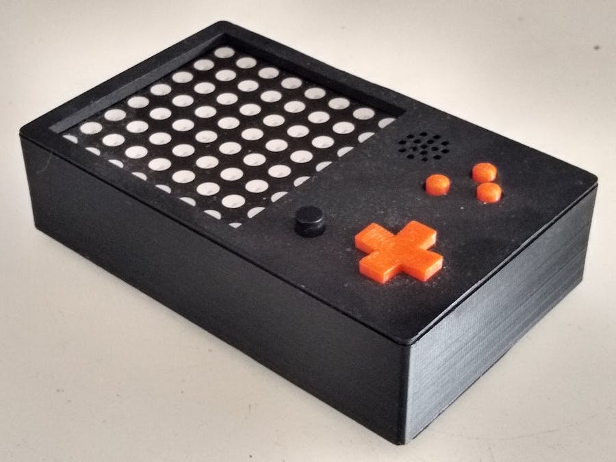
So my first task was to create a game console that I would ultimately code Othello on. The game lends itself to a two color 8x8 matrix so that was an easy choice for the display. The player needs to be able to select any square on the board. So this meant either a joystick or X-Pad. I choose the X-Pad because the joystick can be difficult to move a cursor to a specific location and has no tactile feedback. To make the game console more generic, I also included three separate buttons which can be used for example as a fire button, help button, start game button etc.
For testing I modified an Asteroids game created by kreck2003 (a fellow Hackster).
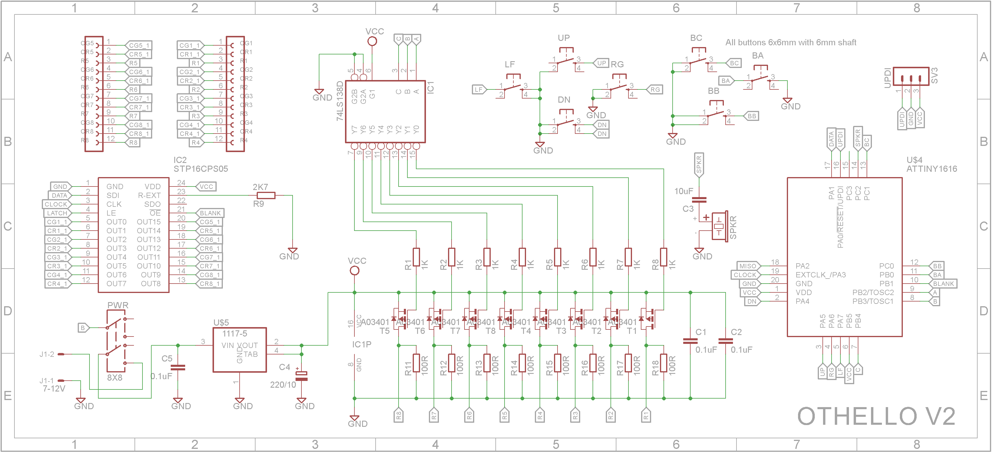
Other GamesDesignThe Red/Green matrix module has a common anode. The matrix has 16 cathodes (8 red and 8 green). The cathodes are connected to a STP16CPS05 16 Channel shift register with each output being a constant current LED driver. The anodes for the matrix is connected to a set of 8 P-Channel MOSFETs which are driven by a 3 to 8 line decoder/driver so as to reduce the pin count needed for the microprocessor.
Each switch on the X-Pad as well as the three separate switches are connected to separate pins on the ATtiny3216 microprocessor. This allows any of the pins to generate a interrupt should the game require it.
A passive buzzer is connected to the microprocessor via a capacitor to isolate any DC component.
A 5V regulator is included so the console can be run from a 7-12V power brick. The console will also run on 3.3V so you could short out the regulator and power it from a lithium-ion 3.7V battery instead.
Using the STL files provided, print the bottom and the top. I used a 0.2mm layer height and no supports.
The Buttons and X-Pad should be printed in a contrasting color. Use a 0.1mm layer height and no supports.
There are four mounts in the top to support the printed circuit board. Drill these out with a 2.5mm drill and create a thread with a 3mm tap.
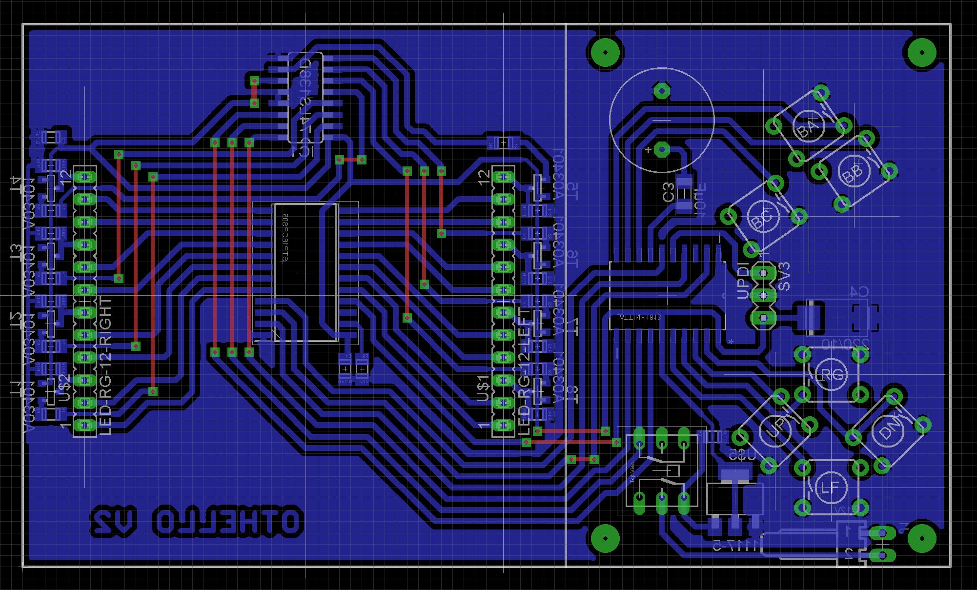
Building the electronicsAll the electronics are mounted on a PCB. With the exception of the buzzer and switches, SMD devices have been used exclusively. The Eagle files have been included should you wish to get the board commercially made or you can make it yourself. I used the Toner method to make mine.
Start by adding the SMD components.
Next add the links if you are using a single sided PCB
Solder on a 3pin header used to program the microprocessor board and the power connector to the copper side of the board. I usually dab a bit of red paint onto the pin header or connector to identify the supply pin.
Add the switches, buzzer and matrix to the component side of the PCB.
Insert the X-pad and 3 buttons into their respective holes and screw the PCB to the top of the case using 4 x 6mm M3 screws.
Upload the code to the ATtiny3216 microprocessor (see next section).
Add a DC panel socket to the bottom of the case and wire up to the power plug. Make sure you test that you have polarity correct before plugging the power plug into the power socket on the PCB.
The ATtiny3216 is part of the new breed of ATtiny microprocessors. Unlike the earlier series such as the ATtiny85, the new breed use the RESET pin to program the CPU. To program it you need a UPDI programmer. I made one using a Arduino Nano. You can find complete build instructions at Create Your Own UPDI Programmer. It also contains the instructions for adding the megaTinyCore boards to your IDE.
Once the board has been installed in the IDE, select it from the Tools menu.
Select the ATtiny3216 board in your IDE
Select Board, chip, clock speed and the COM port that the Arduino Nano is connected to.
The Programmer needs to be set to jtag2updi (megaTinyCore).
Open the sketch and upload it to the ATtiny3216.
Software (Display.h)The Display.h contains most of the functions needed to handle the display. It has it's own namespace so every function or variable needs to be prefixed with srn::
CMODE color is a color constant used to specify a color on a number of functions. Its value is either srn::C_BLACK, srn::C_RED, srn::C_GRN or srn::C_ORG
Coordinates (x, y or column, row) are always zero based (i.e. 0 to 7). Column 0 being farthest left and Column 7 being farthest right. Row 0 is the top row and Row 7 is the bottom row.
srn::setup() - Call this in your setup() function before you use it
srn::refresh() - Transfers the display buffer onto the actual matrix.
srn::drawString(String s, CMODE color) - Scrolls text across the screen in the specified color. The variable srn::scrollDelay is zero when the string has scrolled off the screen. Setting this variable to zero will stop any scrolling.
srn::drawCharacter(int8_t x, char ch, CMODE color) - Draws a letter on the display buffer starting at column x. Characters are always drawn on rows 1 to 7.
srn::setPixel(int8_t r, int8_t c, CMODE color) - Sets the pixel in the display buffer at row r, column c to the specified color. Use srn::C_BLACK to erase a pixel.
srn::getPixel(int8_t r, int8_t c) - Returns the color of the pixel at row r, column c from the display buffer. The color will be one of the CMODE constants.
srn::clearDisplay() - Clears out the display buffer. Note you need to also call srn::refresh() to have it reflected on the matrix screen.
Pin mappingUse the following defines to access the switches and buzzer in your source code.
#define SW_BA 9        //PB0
#define SW_BB 10       //PC0
#define SW_BC 11       //PC1
#define SW_LF 3        //PA7
#define SW_RG 2        //PA6
#define SW_UP 1        //PA5
#define SW_DN 0        //PA4
#define SPEAKER 12     //PC2
The SPEAKER pin should be setup as an OUTPUT
pinMode(SPEAKER, OUTPUT);
The switch pins should be setup as INPUT_PULLUP
pinMode(SW_BA, INPUT_PULLUP);
The switches are active LOW. That is digitalRead(SW_BA) is LOW when the A button is pressed.
Next stepsNow that I have a generic game console, the next step is to write the Othello game. I will publish this as a separate project when it is complete.


Comments
Please log in or sign up to comment.