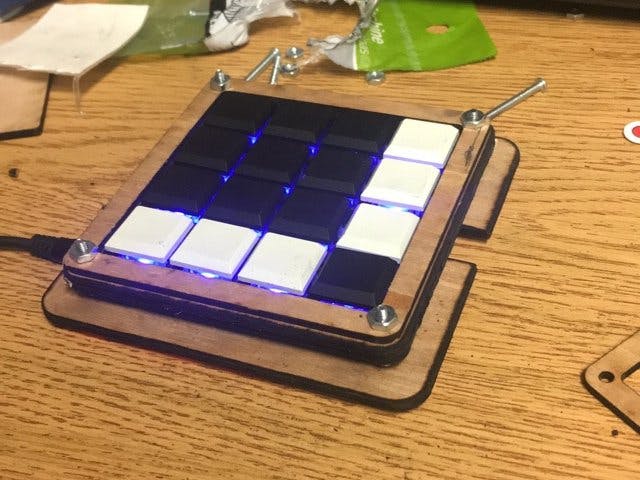
This is a 4x4 keypad that I designed and built in my first year of college. My intent for this project was to use it as an external number pad/macro pad for my laptop. It also doubles, as a good controller to play games or control a robot with.
While working on this project I learned a lot about PCB design: from creating the schematic to laying out the components and connecting everything together. I also got insight to how commercial grade keyboards are made.
In addition, I developed different practical skills, like, laser cutting, hand soldering parts, and utilizing data sheets.
Here are some early version's of the project that lead me to produce what I have now
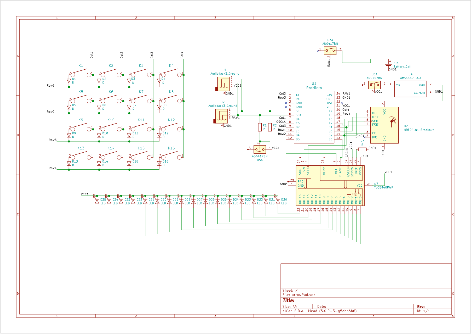
The keyboards is controlled by using a 4x4 switch matrix. This allows the Pro Micro to read 16 different keys while only taking up 8 pins. As opposed to wiring each individual key to its own pin on the micro controller, which would take up 16.
To check key presses the microcontroller first selects a row, then looks at each individual column. After each column for the row has been checked, it repeats this for the rest of the rows. When this sequence is run very quickly (this keyboard runs it ~60 times/sec) it reads the keys accurately and responsively. Since the keyboard reads all the keys 60 times/sec, the maximum delay for a key press is 1/60th a second (17ms). This also means that in order to get a misreading, the user would have to push and release the key in less than 1/60th a second (17ms) and also do it in the gap where that specific key is not being read.
There are diodes placed after each switch to prevent current from going back into the switch and cause unwanted presses.
With bigger and bigger keyboards, using a matrix is the practical options as as the ratio between number of keys to pins used increases drastically 6x6 =36, 8x8 = 64, 10 x 10 = 100, etc...
LightingAfter adding the keyboard matrix, I only had 3 pins free (excluding the SPI and i2c pins), however I still had to control 16 LEDs. In order to extend my pins I used the Texas Instruments TLC5940 led driver. The TLC5940 gets connected to the SPI bus along with 3 PWM pins. This driver allows the pro micro to control 16 LEDs with PWM. I controlled the driver with the Arduino TLC5940 library. Note: using this library requires the 3 PWM pins to be specific ones on the Arduino(shown on schematic). In addition, when using the TLC5940 library you must choose the correct board in the config file (Arduino -> Libraries -> TLC5940 -> pinouts ->chip_includes.h) In this case uncomment "include "ATmega_xx4.h"" since the pro micro is based off of the ATmega32u4.
void readBoard(){
 for(int i = 0; i < rowSize; i++){
   pinMode(row[i], OUTPUT);
   digitalWrite(row[i], LOW);
   for(int j = 0; j < colSize; j++){
     pinMode(col[j], INPUT_PULLUP);
     keysState[j][i] = digitalRead(col[j]);
     pinMode(col[j], INPUT);
   }
   pinMode(row[i], INPUT);
 }
}
This is the process for checking key presses, it works as follows. Select a row pin and set it to LOW, allowing current to flow through. Then make the a column an input and connect it to a pull-up resistor. If a key is pressed in the selected rows and column, then current fill flow to the row pin that is set to low, causing the column input to go from HIGH to LOW. The value of each key is updated in the keysSate array on each iteration. Once all the columns are finished, it will go to the next row and repeat.
int ledMap[] = {7,6,4,5,11,10,9,8,15,14,13,12,0,1,2,3};

void setCol(int c, int val){ //Sets a column to a passed value
 for(int i = c; i <= 16; i+=4){
   Tlc.set(ledMap[i], val);
 }
}

void setAll(int x){
 for (int i = 0; i < 16; i++) { //sets all the keys to a passed value
   Tlc.set(i, x);
 }
}
In my code I used an array called ledMap which maps provides an easier way to refer to keys. For example ledMap[0] will refer to the key in the top left, ledMap[1] will refer to the key right of it,... and ledMap[15] will refer to the key at the bottom right. Having ordering makes it easier to work with, like making setCol() much easier to write.
PCBI used KiCad to make the schematic and make the PCB. The PCB has mounting holes for #4-40 screws. The PCB also uses sockets so different mechanical switches can be swapped in and out.
The PCB also features a spot for a headphone jack, which allows one keypad to be connect to the other. The jack has 4 lines, power, ground, and 2 for the i2c bus.
R1 and R2 = 4.7k resistor (i2c pull up)
R3 = 10k (for tlc5940)
The housing uses wood that is 1/8 inches (~3.1mm) thick. With that, #4-40 screws that are 3/4 inch are enough to hold everything together.
Auto cad files


_4YUDWziWQ8.png?auto=compress%2Cformat&w=48&h=48&fit=fill&bg=ffffff)


_Ujn5WoVOOu.png?auto=compress%2Cformat&w=40&h=40&fit=fillmax&bg=fff&dpr=2)
_3u05Tpwasz.png?auto=compress%2Cformat&w=40&h=40&fit=fillmax&bg=fff&dpr=2)

Comments
Please log in or sign up to comment.