


Hardware components | ||||||
 |
| × | 1 | |||
 |
| × | 1 | |||
 |
| × | 1 | |||
 |
| × | 1 | |||
Software apps and online services | ||||||
 |
| |||||
Getting to know how to plot a graph on the ThingsAI.io platform. It is an IoT platform, the best platform I have ever seen for beginners. It is the best IoT platform which supports many devices like NodeMCU, Raspberry Pi, ESP8266, and others.
Here we are going to use a NodeMCU and program it with Arduino IDE.
NodeMCU is a LUA-based interactive firmware for Espressif ESP8622 Wi-Fi SoC, as well as an open source hardware board that contrary to the $3 ESP8266 Wi-Fi modules includes a CP2102 TTL to USB chip for programming and debugging, is breadboard-friendly, and can simply be powered via its micro USB port.
This module is one of the cheapest available wifi-modules in market. V3 or Version3 is the latest version of this module. This tutorial however will facilitate you to connect all the versions of ESP8266 NodeMcu, i.e V1, V2 or V3.
For makers, having ESP-12 module, rest assured, 12E is no different from its precursor. The only difference : 6 extra GPIOs are present in ESP-12E
Headers: 15-pin header with access to GPIOs, SPI, UART, ADC, and power pins.
Power: 5V via micro USB port
NodeMCUPIN OUT Diagram
(Scroll left to get all image of the hardware.)
-
Software RequiredSoftware Configure for This Project
Here you have to know how to use NodeMCU and get the performed functions accordingly your requirements. Just learn this steps and get know about its function step.
Step 1: Connect the NodeMcu board to the system using usb cable and Go To (Tools>Board>Board Manager) in your Arduino IDE.
Step 2: Now search for NodeMCU 12E and select it... and then Select the PORT of the device if everything is installed properly it will select automatically. If not Go to "My Computer " on your pc desktop and click right and go to and check the port number of NodeMCU.
Step 3: After Confirming the PORT, Now its time to manage required libraries file for this project. Go To File>Preferences
Copy and Paste the link as in image shown... http://arduino.esp8266.com/stable/package_esp8266com_index.json
Step 4: Open the IDE and click to the "Sketch" menu and then Include Library > Manage Libraries
Step 5: Search for NodeMCU and similarly follow this step and repeat untill you installed all libraries required.
Nowcopy the code from below code given at last of this tutorial and Compile it And Upload it to board.
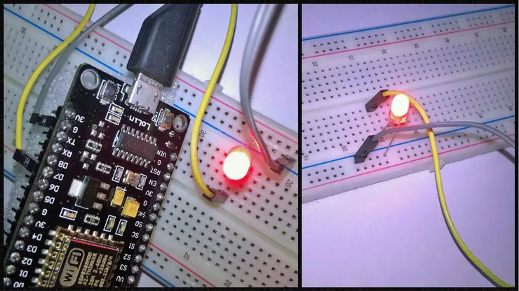
Hardware Connections
As the GPIO13 is at pin D7 of NodeMCU so connect the positive pin of LED with This and Then Connect the GND pin to the negative of the NodeMCU.
For Detail information
proect click here https://youtu.be/7Gp43-jxfT0
Graph Obtained at ThingsAI.io Platform Dashboard.


Comments
Please log in or sign up to comment.