Based on Application Note 3641 – available here.
When I was in college, I was friends with one of the lab engineers that managed the electronics labs in the department. One of the problems that he worked on was to count students in a room in order to quantify lab usage over time. There are many approaches to this problem – visual cameras, radar sensors, door switches, etc… However, the solution would also have to be compliant with laws regarding privacy and be installable without damaging the lab space – this meant that some solutions, such as visual cameras, were almost immediately off the table.
While he has since retired, the problem is still an interesting exercise. One possible way to solve this problem would be to use a Passive Infra-Red (PIR) Sensor. PIR sensors passively absorb IR radiation in the field of view of the sensor. When the amount of IR in the environment shifts, the sensor’s output changes. This appears as a small AC signal on a large DC bias. By monitoring the differential voltage, which cancels out the DC offset, changes in the environment can be detected.
The ATtiny1627 family of microcontrollers contains a differential Analog-to-Digital Converter (ADC) with a programmable gain amplifier (PGA), which can provide the sensitive analog interface for this sensor. The ADC in the ATtiny1627 family can reach a maximum resolution of 17-bits via oversampling, however it is normally used at 12-bit resolutions.
Video OverviewAnalog Sensor Conditioning and InterfacingStandard single-ended ADCs cannot reliably measure a PIR sensor directly. The AC signal (when present) is extremely small, and the DC bias is very large. One solution for this is to treat the PIR sensor output as a differential signal, rather than a signal measured with respect to ground.
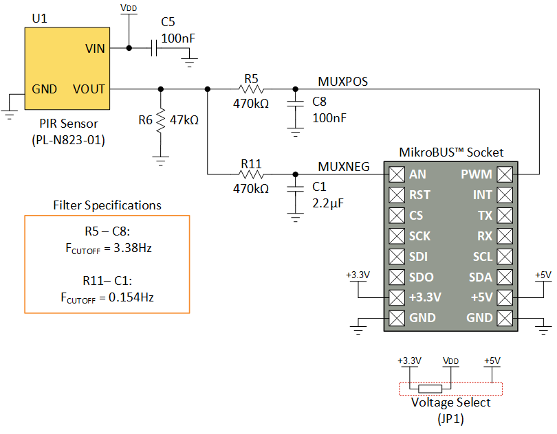
Before the signal enters the ATtiny1627 for differential amplification and measurement, two RC low-pass filters (at differing roll-off frequencies) are used to create the “positive” and “negative” components of the differential signal.
The positive-side RC filter is built from a 470kΩ ohm resistor and a 100nF capacitor for a cutoff frequency of 3.38Hz. This filter lets the AC signal from the PIR sensor along with the DC bias through while blocking high-frequency noise.
The negative-side RC filter is built from a 470kΩ resistor and a 2.2µF capacitor for a cutoff frequency of 0.154Hz. This filter is designed to pass the DC bias while rejecting the AC signal from the PIR sensor.
The two low-pass filters create an effective bandpass filter –frequencies lower than the cutoff frequency of both filters appear on both inputs (minus any losses from the filters). Since the ADC is differential, these signals are subtracted out. Signals that are higher than both cutoff frequencies are heavily attenuated by the RC filters, which minimizes their effects. Finally, signals that are attenuated by one filter and passed by the other will be the strongest input signal. The image below shows a simulation of the filter response in MPLAB® Mindi™ Analog Simulator.
On startup, the ATtiny1627 initializes the peripherals in use:
- Differential ADC with PGA
- Periodic Interrupt Timer (PIT)
- Event System (EVSYS)
- USART (for serial communications, if enabled)
Then the microcontroller enters a warmup phase where it initializes 2 digital filters on the device – a short-term averaging filter and a long-term averaging filter. These filters are used to detect motion over time. During warmup, the LED flashes at 1Hz.
After initializing the peripherals and digital filters, the microcontroller enters sleep. In sleep, the power consumption of the microcontroller is very low, which extends battery life (for more information about power consumption with various settings, please consult the Application Note). The ADC is periodically triggered without waking the microcontroller through the PIT signal connected in the Event System.
After performing the conversion(s), the ADC wakes up the microcontroller by triggering an interrupt. The microcontroller updates the digital filters with the value from the ADC. To determine if motion has occurred, the microcontroller compares the difference between the long-term and short-term filters to see if it passes a threshold. If the threshold is exceeded, then motion is detected, and the LED I/O line is connected to a 4 Hz signal from the PIT.
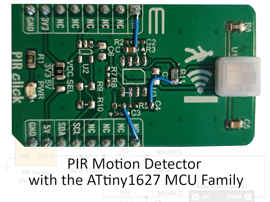
To demonstrate this application, the PIR Click Board™ from MikroE was used as the starting point. This board filters, amplifies, and measures (via an included ADC), the output from the PIR sensor. However, the ATtiny1627 does not need most of these parts – 2 OPAMPs, 6 resistors, and 4 capacitors can be removed from the parts list of this board by using the internal differential ADC with PGA. (Note: These instructions also remove the included 12-bit ADC and associated components.)
Warning: Modify your development board at your own risk!
First, remove the following parts from the click board:
- R2, R3, R4, R5, R7, R8, R9, R10, R11, and R12 - (Optional) R1 can also be removed to save power
- U2 and U3
- C1, C2, C3, C6, and C7
Then, add the following parts to the footprints:
- R5 = 470kΩ resistor
- R8 = 100nF capacitor
- R11 = 470kΩ resistor
- C1 = 2.2µF capacitor
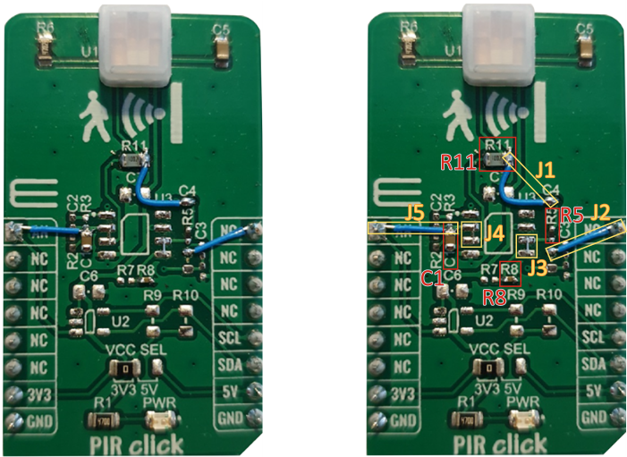
Once all parts have been installed, add the following jumpers and shorts (see the image below for a visual guide):
- J1: Connect the right side of R11 to the top pad of C4
- J2: Connect the top pad of R4 to the top right pin (labeled NC) of the header
- J3: Short the right-side bottom two pads of U3
- J4: Short the left-side middle two pads of U3
- J5: Connect the top pad of C1 to the top left pin (labeled AN) of the header
With the power off, insert the modified board and the ATtiny1627 Curiosity Nano as shown:
Next, connect the Curiosity Nano to your PC with a USB cable.
Programming the Curiosity NanoFirst, grab a copy of the code example from Github, then unzip the downloaded folder. Launch Microchip Studio (formerly Atmel Studio) and open the project. Compile and program the ATtiny1627. If everything was successful, waving or walking in front of the sensor should cause the LED on-board to flash.
Program OptionsInside this program, there are a few settings that can be enabled or adjusted to debug or to interface with other PIR sensors:
- PIR_OVERSAMPLE_RATE – Sets how many samples are collected by the ADC before waking up. Affects the resolution of the ADC and noise rejection.
- PIR_SAMPLE_RATE_PER_SECOND – Sets how many times the ADC is woken up to collect samples. Affects the latency of the application.
- PIR_PGA_GAIN – Sets the gain of the PGA inside the ADC. Changing this value will affect the scale of the signal.
- PIR_DETECTION_THRESHOLD – Sets the threshold for detecting motion. If the sensor fails to detect motion, or detects motion when there is none, this value should be adjusted.
- PIR_WARMUP_TIME_MS – Sets the delay time for the PIR sensor to warmup, if needed.
- PIR_LONG_TERM_FILTER_RANGE – Sets the number of samples the long-term filter averages with.
- PIR_SHORT_TERM_FILTER_RANGE – Sets the number of samples the short-term filter averages with.
- PIR_DEBUG_MESSAGES – When uncommented, this macro enables UART debugging messages to the PC. MPLAB Data Visualizer can be used to view this data (see section below).
MPLAB Data Visualizer is a free plugin that displays data from a Virtual COM port in a terminal window or a graph. In this application, enabling PIR_DEBUG_MESSAGES will cause the ATtiny1627 microcontroller to send data through the on-board programmer to the PC.
The video below shows how to begin viewing the debugging information by loading the included data streamer configuration.
Kjetil Kirkholt


_9RZTEQKk4A.png?auto=compress%2Cformat&w=48&h=48&fit=fill&bg=ffffff)


Comments
Please log in or sign up to comment.