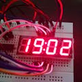
LED matrix with MAX7219 are very versatile and can be used in several projects with Arduino.
In this case, I used it to simulate an analog clock without its hands, with very interesting results. The hours and minutes are placed around the center of matrix giving a familiar look of analog clocks. The code I have developed applies a little of trigonometry (sine and cosine) to calculate the coordinates of hours and minutes to be shown into LED matrix. With that I saved many lines of coding.
The assembly is very simple using few components and you will have no problems to work on it.
Let's do it!
The material you need is shown in the following list:
- Arduino UNO R3
- Module of LED Matrix with MAX7219 (Maxim Integrated)
- Tactile Push Buttons (02 x)
- Breadboard (small size)
- Jumper Wires
- Paper template to cover the LED Matrix (see attached file for printing)
Note: This project uses the Arduino internal clock. It is not so accurate as an external RTC (Real Time Clock), but for the purposes of this project, it works very well.
The schematic is attached and you should follow it closely for the jumpers connections.
After starting, the default time shown is 00:00 hs.
For adjustments there are only two tactile buttons to perform the setup of time:
- Setup of Hours
- Setup of Minutes
Just keep it pressed for adjustments.
The hours are shown in the display by numbers between 1 and 12. The minutes are shown by numbers between 0 and 55 in steps of 5 minutes.
In the last column of display is shown the fractional minutes from 1 to 4 that must be added to the minutes shown in the main template of clock.
In the middle of display, there is an LED blinking each second and there are also two LEDs for AM and PM indication.


_ztBMuBhMHo.jpg?auto=compress%2Cformat&w=48&h=48&fit=fill&bg=ffffff)


_1x_bGT19vVAby.png?auto=compress%2Cformat&w=40&h=40&fit=fillmax&bg=fff&dpr=2)
_3u05Tpwasz.png?auto=compress%2Cformat&w=40&h=40&fit=fillmax&bg=fff&dpr=2)
Comments