


Hardware components | ||||||
| × | 1 | ||||
 |
| × | 1 | |||
 |
| × | 1 | |||
| × | 1 | ||||
| × | 1 | ||||
| × | 1 | ||||
| × | 1 | ||||
| × | 1 | ||||
| × | 4 | ||||
| × | 8 | ||||
| × | 4 | ||||
| × | 4 | ||||
| × | 1 | ||||
Today's trend in implementing lighting systems is mostly towards utilizing LED components which brings order of magnitude better efficiency compared to classical Incandescent light bulbs. Recent years there is advancement in LED technology resulting in so called "High brightness LEDs" with increased efficiency but these LEDs require to be driven by large currents usually few amps what presents challenge in implementing driving circuit. Classical lighting LEDs are usually driven by currents bellow 300mA and desired power is achieved by series connection of many of them and there are plenty of driver boards on market. However there is lack of high current driver boards required for high brightness LEDs. In this project it is presented how to easily build Smart lighting system that utilizes high brightness LEDs consisted of: Raspberry Pi Zero computer (as controller), PiJuice Zero W UPS HAT for Raspberry Pi, LED driver circuit, High brightness LED Board, Light control Server (Software) and Light control application (User Interface).
Raspberry Pi Zero W (Rpi Zero) is single board Linux computer featuring WiFi and Bluetooth with cost of only $10. It has small dimensions (30 x 65 mm), can fit in tight space and is expandable with boards called HATs what makes it pretty interesting for customized (DIY) Internet of Things systems. Plenty of HATs and open frame boards are on the market like environmental, motion or proximity sensors and all of these are easily connected with Rpi Zero and programmable in high level programming languages like Python or JavaScript. This makes Rpi Zero based lighting controller as perfect choice with great potential for smart lighting functionality.
PiJuice Zero (smaller version of PiJuice HAT) is UPS HAT for Raspberry Pi that integrates power management features like battery charging/discharging keeping Raspberry Pi and system peripherals powered even when there is interruption in electricity or charging battery directly from solar panel for complete off-grid application. One of the interesting features utilized in this project is system power output provided through programmatically controlled system switch that can provide up to 2.1 amperes to peripheral (in this case LED). This enables switching LED on/off from application. Other PiJuice feature used are IO pins that can be configured to output PWM signals and it is used to drive MOSFET transistor and in that way controls LED current (Brightness). All these features are accessed and configured through high level python software API.
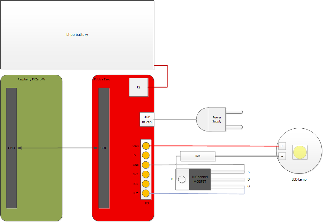
LED driver circuit is implemented using N channel MOSFET transistor and current limiting resistor. MOSFET is controlled with PWM signal from PiJuice (IO2) see schematic (Image 1). Light level control is accomplished by controlling duty cycle of PWM signal.
LED Lamp chosen is based on high brightness Warm White 2700K LED with maximum current of 3A. However there are other versions that can be used instead like Cool or Neutral White, or even color LEDs (Red, Green or Blue) interesting for decorative lighting or Christmas Lights. Here are listed some alternatives:
- XPLAWT-00-0000-000BV50E5-SB01 - Neutral White, 4000K
- XPLAWT-00-0000-0000V60E1-SB01 - Cool White, 6500K
- XPEBBL-L1-0000-00301-SB01 - Blue
- XPEBGR-L1-0000-00F03-SB01 - Green
- MTG7-001I-XBD00-RD-0701 - Red
For Blue or Green 1 ohm and for Red 2.2 ohm current limit resistor should be used instead of 0.47 ohm listed, in order to limit maximum current below maximum rated.
Light control Server pjlight.py is python script running on Raspberry Pi Zero W and is based on Tornado Websockets python library. Server interfaces to PiJuice by controlling PWM signal and system switch and serves commands sent from control application like toggle light state or set brightness.
Light control application index.html is Html page that implements high level GUI for light control. When loaded it connects to Light control server and sends light control signals using the Websockets protocol.
It is supposed that you own basic soldering equipment. Follow these steps in order to solder driver circuit to PiJuice Zero board:
a. Use cable from part list, cut out connector attached (not needed) and solder black wire to - terminal on LED board, red wire to + terminal on LED board, see Image2.
b. Bend pins 1(gate) and 3(source) of MOSFET transistor so it lays horizontally in holes IO2 and GND of P3 unpopulated header on PiJuice board, see Image2b.
c. Solder MOSFET pins 1 and 3 to PiJuice board from top side and cut out excessive pin lengths on bottom side like on Image2c.
d. Solder Current Limiting Resistor to Case (drain) of MOSFET transistor and cut out excessive pin lengths like on Image 2d.
e. Solder LED Lamp, red wire to VSYS hole of PiJuice board (P3 header), black wire to free end of current limiting resistor like on Image2e.
As we have prepared PiJuice Zero with driver circuit and LED Lamp soldered we now can connect PiJuice board to Raspberry Pi Zero W. First mount M2.5 4mm spacers (top side) using M2.5 12mm bolts and M2.5 nuts (bottom side), see Image3. Put small piece of isolation tape over HDMI connector so it prevents shorting gate pin of MOSFET transistor soldered to PiJuice to touch grounded connector below.
On top of spacers put 0.5mm washers so we get total board-to-board height of 4.5mm. Now align and push PiJuice board on top of Raspberry Pi Zero and fix it with M2.5 nuts.
5000mAh Li-po battery should be connected to J2 connector on PiJuice board. Power supply should be connected to micro USB connector on PiJuice board. Fully assembled and connected system is shown on Image4.
Note LED board at maximum power level can become hot and it is recommended to mount LED Lamp to some heat conducting surface or aluminum case/heatsink, not provided in this project.
Software setupWrite Linux Image. Download Raspbian Lite Linux image from official site and unzip. Put microSD card into PC, use Win32 Disk Imager to write downloaded Raspbian (unzipped) image to card and wait for writing to finish. After finish, if successful boot fat32 partition should be auto-mounted (win 10), if not try reinserting card.
Install. Copy attached pjlight.py script, index.html and service config file pjlight.service to microSD boot directory (on PC).
Enable SSH. Make empty file with name ssh in boot directory, or just copy one existing small file already in boot directory and rename it to ssh. This will enable ssh connection from PC to Raspberry Pi Zero.
WiFi Setup. Create text file called wpa_supplicant.conf and copy content below into it replacing WIFI_SSID and WIFI_PASSWORD with ssid and password of your wifi network.
country=UK
ctrl_interface=DIR=/var/run/wpa_supplicant GROUP=netdev
update_config=1
network={
ssid="WIFI_SSID"
scan_ssid=1
psk="WIFI_PASSWORD"
key_mgmt=WPA-PSK
}
Boot system. Remove microSD from PC and insert into Raspberry Pi Zero W (battery and power should be disconnected). Connect battery and power supply to PiJuice Zero (assembled on top of Rpi as described). Push power button (SW1) on PiJuice Zero to start system.
Establish SSH connection. On Win PC you can use programs like putty and for this you will need to login using address pi@raspberrypi.local, port: 22 and default password: raspberry. After successful login reboot with command:
sudo rebootwait for reboot 1 minute and then login again.
Install PiJuice Software. Type:
sudo apt-get update
sudo apt-get install pijuice-base
and wait for installation to finish.
Then test it is installed and works correctly, type:
pijuice_clifor more info about PiJuice software and client tool visit official page.
Configure PiJuice. In this project we use 5000mAh battery that is not by default configured in PiJuice, so we need to set profile for 5000mAh Li-po battery. Use pijuice_cli tool, navigate to Battery profile menu and select PJLIOPO_5000 battery profile, see Image5.
Install Tornado Server. First install pip3:
sudo apt-get -y install python3-pipthen run:
sudo pip3 install tornadoRunServer. Type:
sudo python3 /boot/pjlight.pyserver should start and will print info on screen.
Enable System Service. If Server starts successfully, we now can create system service to automatically run server every time system boots. Click Ctrl+c to exit server and type four commands below:
sudo mv /boot/pjlight.service /lib/systemd/system/
sudo chmod 644 /lib/systemd/system/pjlight.service
sudo systemctl enable /lib/systemd/system/pjlight.service
sudo systemctl start pjlight.service
And that's it, system now is ready to be accessed by web application from different devices like PC or Cell phone connected to same local network.
Web ApplicationAfter successful setup, it is time to test this lighting system using web application. Open web browser on phone or PC and type address pi@raspberrypi.local, and web application should be loaded like on Image6. If successfully connected to Lighting Server, it will show message "Connected to: ws://raspberrypi.local/pjlight". You can now click "ON/OFF" button to toggle light state, or move slider to adjust brightness.
Smart Lighting system based on Raspberry Pi Zero W and PiJuice Zero utilizing high brightness LEDs is presented with great potential to be used in different types of Lighting applications like off-grid lighting, uninterruptible lighting decorative lighting, smart home lighting. It can provide up to 5W of LED power with dimming function down to zero.


Comments
Please log in or sign up to comment.