


Hardware components | ||||||
| × | 1 | ||||
Hand tools and fabrication machines | ||||||
 |
| |||||
Hi! Today we are gonna to build a star electronic kit. This is a newest version of the star single-chip soldering kit, which adopts two-sided wiring design and beep music- there are pads on both sides, one side is only for soldering the fog LED lights, and the other side is for soldering chip, switch, and buzzer light. That makes structure simple and beautiful.
VOGURTIME Star Electronic soldering Kit is an entry-level 51 MCU production kit that takes you into the world of MCUs, may you fall in love with MCUs! This kit is suitable for a wide range of beginners and electronics enthusiasts. The program has been programmed into the MCU before shipment. The program has a variety of color LED rotation flashing mode and 11 pieces of music. Of course, it can be a nice present and adornment for your family and friends.
DON'T MISS IT IF YOUR LOVELY KIDS ARE LEARNING ELECTRONICS RECENTLY!
1. Overview1> Name:VOGURTIME Colorful Music Star DIY Kit
2> PCB Size:7.5cm x 8cm x 0.2cm
3> Finished with Shell Size:8.5cm x 9cm x 2.1cm
4> Work Voltage:DC3.5 – 5.5V 100mA
5> Powered by: Power bank/power adapter/computer USB/battery
6> Control mode: Key control
7> PCB Material: FR-4 military grade A material plate
8> Basic Function: LED shining and changing; Beep music
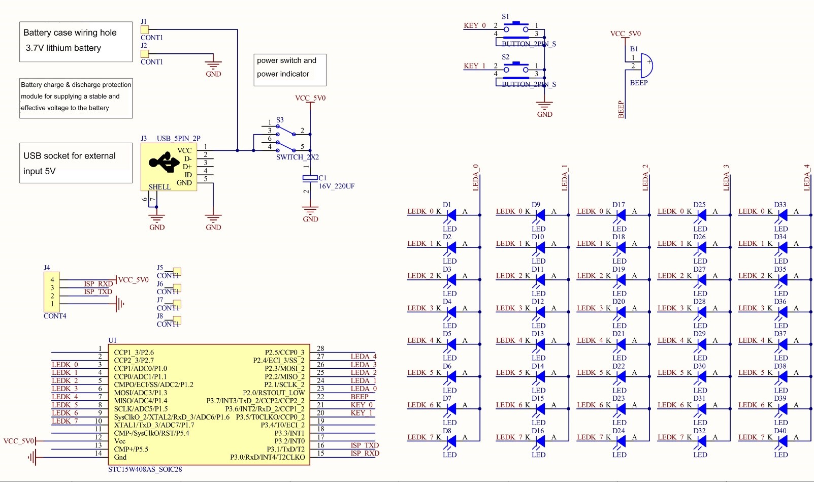
2. Components showThe PCB needs to be two-sided welded. The following steps are the example of the back soldered firstly. There are various component identification symbols is the back.
3. Let's start to solder!You could have your own soldering steps too. It is not difficult for soldering, just pay attention to several points would be great. It is really nice for learners.
3.1> I'd like to start soldering from little components. Here solder the USB. Please note: The USB has five pins, because the feet are relatively close and 3 are not used. In order to prevent short circuit caused by soldering, the middle 3 pins no need to be soldered, as shown at below.
3.2> For soldering electrolytic capacitors, pay attention to the positive and negative poles. Insert the long pin into the hole of the + and the short leg into the hole of the -.
3.3> Solder the tactile switch and install it on the PCB at S1 and S2; Solder the buzzer. The buzzer indicates the + sign, but this is a passive buzzer, which can be installed regardless of the positive and negative poles. 5>. Solder the power switch.
3.4>. Install the IC socket. The IC socket should be mounted and soldered to the notch position of the symbol on the PCB board. Note that the solder joints of the base should not be too large to affect the LED lights installed on the front side. The chip is not installed temporarily.
3.5> Well, let's turn it over and solder the LEDs which will flashing rainbow color.
Pay attention to the positive and negative poles. We put more 4 extra LEDs in case you need it. The long leg of the LED is inserted into the + hole, and the short leg is inserted into the - hole. You could leave a certain length of the pin to bend the lamp bead if it is needed (when installation the shell), as shown below,
We finished soldering here, it's easy. let's try to plug the 5v power into the kit to see if it works well. If no, please carefully check the solder joints.
4.Yes, :) Let's install the acrylic shell.
4.1> First, let's install the copper column like this,
4.2> Remove the protective paper of the shell surface. Please note that there are holes in the front transparent plate, holes and LED lights could be one-to-one correspondence. If some LED lights and holes in the shell do not match, please gently bend or organize the LEDs. Sometimes we may not know how to place the side shell for the switches. Try flipping the side transparent plate up and down or left and right to match the position of the switches. We believe that you will find a perfect way to finish your star kit soon.
At night, Let's starmusic shining!!
Hope you like it! Click ELECTRONIC STAR KIT to have it soon:)


Comments
Please log in or sign up to comment.