


Hardware components | ||||||
 |
| × | 1 | |||
The LinkIt ONE development board is an open source, high performance board for prototyping Wearable and IoT devices. It's based on the world's leading Soc for Wearable, MediaTek Aster (MT2502) combined with high performance Wi-Fi (MT5931) and GPS (MT3332) hipsets to provide you with access to all the features of MediaTek LinkIt. It also provides similar pin-out features to Arduino boards, aking it easy for you to connect to various sensors, peripherals, and Arduino shields.
Thanks to the Wi-Fi and GPRS function, LinkIt ONE is very fit for IoT solution. Here We will use LinkIt ONE to make a IoT demo.
With this demo, we can:
- Display household temperature, humidity, luminosity, volume control data collection on OLED screen
- Cloud service, data uploaded to Cloud platform Xively, real-time monitoring
- Data retention for reviewing how data changes over time
- Remote control Household Appliances by sending a message
- Table Lamp, 3D Printing, controlled by your phone
Prepare the Stuff
Here we use LinkIt ONE as the controller, it's a very powerful board with GPRS and Wi-Fi.
Besides, We need some sensor:
- Grove - Light Sensor
- Grove - Sound Sensor
- Grove - Temperature&Humidity Sensor Pro
And a Display:
- Grove - OLED Display 0.96''
As well as a relay to control the lamp:
- Grove - Relay
To fix all things together, we need a Skeleton Box and some screw and nut.
Hardware Connection
Thanks to the easy-to-use Grove, the connection is very easy.
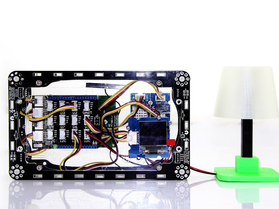
First, we need to fix the grove to the acrylic of a skeleton box:
Then we insert a Sim card to the bottom of LinkIt ONE, and then fix it to the acrylic:
Fix the OLED to another piece of acrylic with some screws and nuts:
Finally, insert Base Shield to LinkIt ONE, and connect all the groves to it:
- Grove - Light Sensor -> A2
- Grove - Sound Sensor -> A0
- Grove - Temp&Humi Sensor -> D2
- Grove - Relay -> 5
- Grove - OLED -> I2C
And fix the 2 side of skeleton box together, hardware is ok now.
3D Print the Lamp
Firstly, we need to download the Shell file here
There are 3 files in it:
- Lamp Part_1.stl
- Lamp Part_2.stl
- Lamp Part_3.stl
You need to print all the 3 parts. When the 3 parts finish printing, you can make it into a Lamp easily.
What's more, you should fix a led and some wire as shown in the above image.
The Code
You can download the code in our github page: please click here.
It's a sketchbook, please click how to use sketchbook.
Open IoT_Demo.ino, and uploade it to LinkIt ONE. If this is your first time to use a LinkIt ONE, please refer to LinkIt ONE Wiki Page.
There are some need to be set in the code, line 48:
// Xively API URL
#define APIKEY "HUQl7E2mC3tJbZoZ3NAPoUffxb2emxCCFJLNu1LROShfZy7u"
#define FEEDID 59487691 // replace your feed ID
#define USERAGENT "chrome" // user agent is the project name
#define WIFI_AUTH LWIFI_WPA
You should have an Xively account first, then make an API Key and the feed id, and write it to the code.
If it's your first time to use Xively, please refer to How to use Xively.
Then you can find a u-disk in your PC.
Create a new .txt file named "wifi.txt", open and edit it:
SSID: your_ssid
KEY: your_key
Save it and switch to USB mode, and reset the system.
Then the demo will run, and you can:
- You can see the data of sensor display in the OLED
- Send "ON" to turn on the lamp, "OFF" to turn off it.
- Goto your xively page to see the sensor data
It's my data, you can take a look: https://xively.com/feeds/59487691#
Humidity:
Light:
Sound:
Temperature:
Make it better
It's just a very simple demo, actually for the IoT application, there's a lot of things to do.
If you have any idea about how to make it better, please make it happen.


Comments
Please log in or sign up to comment.