

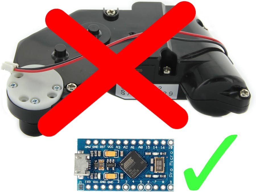
Hardware components | ||||||
| × | 1 | ||||
| × | 3 | ||||
| × | 1 | ||||
| × | 2 | ||||
Software apps and online services | ||||||
 |
| |||||
We have a Hitachi ED-A101 projector. It has a moving mirror, i.e. when it turns on, the mirror opens, and when it turns off, the mirror closes. For this to work, the projector has a DC motor, plastic gears and a metal axe for one of the gears. It is not a good combination, that plastic gear easily wears out because of the sharp edges of the axe. This is a typical problem with this projector, see for example:
We tried to repair the gears (it is not easy to replace the gearbox), we even printed that gear, but it did not work for too long. So we tought of solving this problem in a different way: fix the mirror and simulate the opening/closing process for the projector.
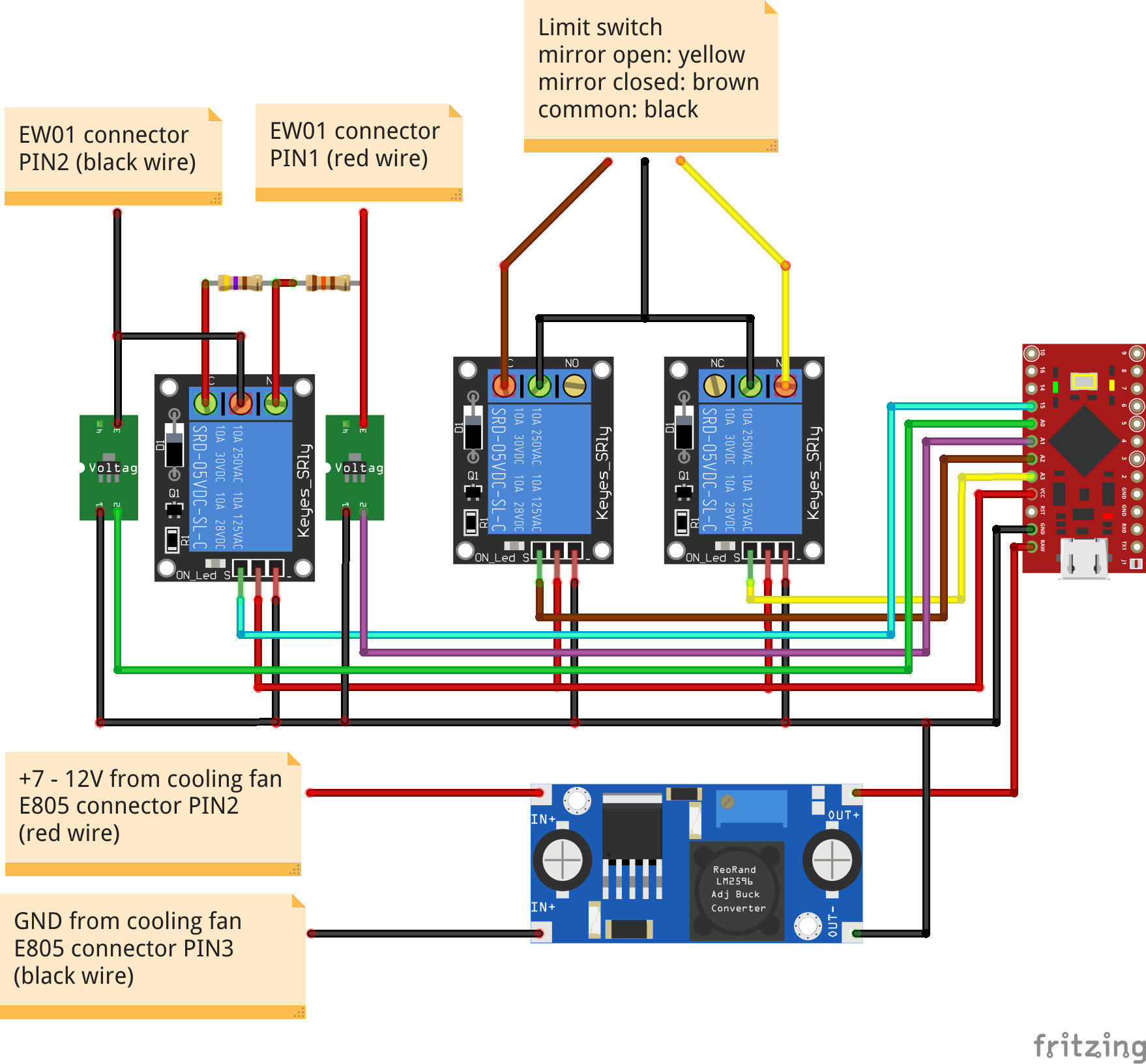
The hardware of the projectorThere are two limit switches on the axe of the mirror reporting the opening and the closing of the mirror to the projector's processor (shown with our cables soldered to it):
Also, the DC motor's and the cooling fan's output pins are marked on this image:
The cooling fan output is used to power the Arduino: it outputs 7-12V depending on the cooling needed. Although Arduino Pro Micro has a RAW input which should handle this range, it turned out (by burning an Arduino :) ), that it is too much for it. That is why we connected the cooling fan's output to Arduino's RAW input through a voltage regulator, which outputs 5.25V independent of the input voltage.
The DC motor output is used to detect when the projector tries to open or close the mirror: it outputs 12V but (naturally) it changes the sides of the + and - depending on whether it opens or closes the mirror. So we connected the two diode-protected stepdown converters' input to the red and black cables of the DC motor output, and the converters' output to the input pins of the Arduino.
The solutionThe first idea was to use two relays to control the limit switches that were connected to the mirror's axe: this should have simulated the opening and closing of the mirror for the projector's processor. We connected everything correctly, wrote the software, but the projector run the DC motor much longer than needed and then always showed an error. Thinking everything over we recognised, that the projector must have some more input that tells it to stop the motor and consider the mirror opened/closed. Since other than the limit switches there were no inputs from the mirror itself, this input must come from the motor in some way. It turned out, that the projector runs the motor until the mirror is forced to the bumper (that is one of the reasons, why the plastic gear wears out easily), so it is always at the same position when opened/closed (since this projector has a reduced throw distance, the mirror's position is critical, the limit switch is not good enough to achieve this precision). Therefore, the projector measures the current used by the motor to detect the final position of the mirror. We also measured the current used by the DC motor, and calculated the resistance of the motor: it was about 600 Ohm while traversing and 140 Ohm on touching the bumper. So, using another relay we connected resistors to the motor output pins of the projector giving just such an amount of resistance at the apropriate times. And it worked... almost... :). After opening the mirror the engineers of Hitachi tried to loosen up the forced gears, so they run the DC motor in the other direction for about 0.05 seconds. In the first version of our program we considered this as the closing of the mirror and, of course, this was an error. And we had another surprise while mounting the projector: it worked just fine with our modification, but when we turned it upside down, it run into an error again. Our guess was, that it senses if it is upside down, and expects a different motor load. Since it would have been much more work to change the resistors, we searched and found the chip sensing gravitation: it is on the panel where the limit switches are. We simply flipped the panel over so that it lies to the projector about gravitation, and the projector works upside down.
The resultThis is how the opening works with this setup:
Notice, that the Arduino turns on with the projector, the blue light on the left indicates the motor output "opening the mirror". The relay leds show (in this order) the opening of the close limit switch, the closing of the open limit switch, and the momentary motor strain, after which the motor output turns off. Looking closely you will see the other blue led flashing for a fraction of a second indicating the loosening of the gears. The closing works similarly:
After soldering everything we placed all components into the empty holes of the projector: the voltage regulator (properly wrapped) next to the lens, the other component under the (closed) mirror. There are screw holes at the bottom of the projector, so we fixed the relays to those, the stepdown converters were glued to the side of one of the relays, and the Arduino (also wrapped) went to the side of the single relay:
The first lines define the IO ports of the Arduino used in this project. If DEBUG is defined, then Arduino reports the actual state of the opening/closing process through its Serial (USB) port.
The opening/closing process has several states. When turned off, the projector is in the CLOSED state: the closing limit switch is closed, then opening limit switch is opened, the motor strain is at 600 Ohm. The _status structure defines how the simulation goes from one state to the next. There are two ways:
- By some timeout: the
timeoutis given is milliseconds, after this time the status changes.
- By some change in the input: if the
ipingoes toistatefor at least 0.2 seconds, then the status changes.
If the status must change, then two things happen:
- If
opinis set to some non-negative value, then the Arduino'sopinpin is set toostate.
- The status changes to
newstatus.
So, from the status structure one can see the following opening process. If the motor tries to open the mirror (for at least 0.2 seconds), the status changes to OPENING1. After 1 second, the closing limit switch is opened and the status changes to OPENING2. After 2 seconds the opening limit switch is closed and the status changes to OPENING3. After 1 seconds the motor strain is closed and the status changes to OPENING4. If the motor stops opening the mirror, then the motor strain is opened and the status changes to OPENED. The closing is similar.
The rest of the code just uses this structure. The variable starttime is used when timeout is specified in the _status structure. The variable cnt is used to delay the recognition of an input change for 0.2 seconds.
This mirror opening system is used in several types of projectors, for example: Hitachi CP-A100, Hitachi CP-A200, Hitachi CP-A52, Hitachi ED-A100, Hitachi ED-A101, Hitachi ED-A110, Hitachi ED-A111, Dukane ImagePro 8100, Dukane ImagePro 8101H, Dukane ImagePro 8103H. With some tuning of the parameters (the timeouts and the resistors) you should be able to use this project to repair those projectors too.
The motor assembly costs about 100 USD and to replace it you must almost completely disassemble the projector. This project costs about 10 USD and you only need to open up the cover of the projector. And you do not have the problematic mirror moving part in the projector any more.


Comments