Download and install the NRF24L01 (http://arduino-info.wikispaces.com/Nrf24L01-2.4GHz-HowTo) and Pro Micro (https://learn.sparkfun.com/tutorials/pro-micro--fio-v3-hookup-guide/installing-windows) Libraries
Story
This project is about the creation of an interactive (touch) board with modular and wireless capabilities. You may ask why someone would want to do this and the answer is, current interactive boards are wired, which means they have to be next or close to the computers that they are controlling. Another problem with current interactive boards is that they come in fixed sizes, something that makes them hard to move and static (if you want a different size, you have to buy a whole new smart board). The final major issue with interactive boards is that they are expensive, with most costing in the thousands of dollars that makes them expensive and inaccessible to most. With the creation of this interactive board, the size and wired constraints are addressed with its wireless and modular features. The issue of price diminishes, considering that this interactive board costs fifty dollars ($50) to produce.
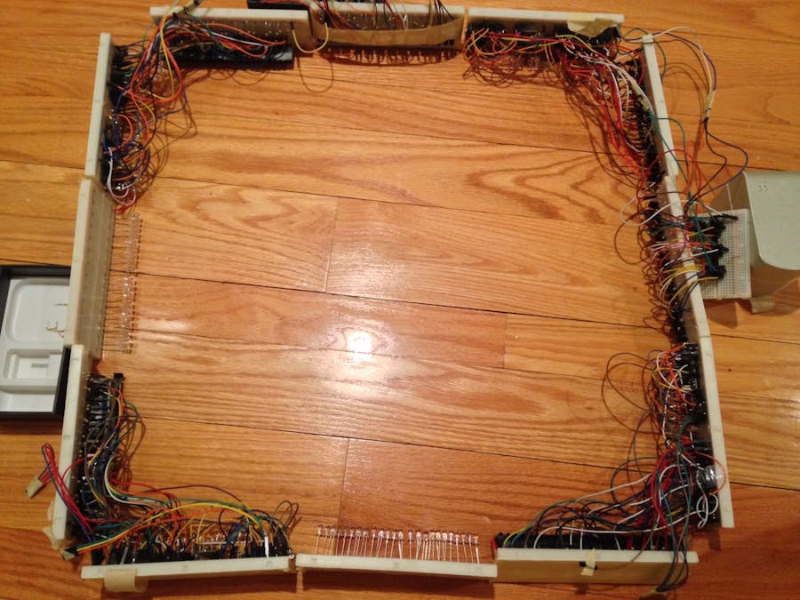
The project is centered on the creation of this interactive touch interface using infrared sensors and emitters. There is a multitude of components involved in this project so to start off, it is best to go over how the main components are connected and how the communicate. Controlling each one of the 4 sensor hubs are Arduino Nanos. The Nanos read data from [24+] infrared phototransistors via multiplexers, as the Nanos only have 8 analog pins and the minimum number of sensors is 24. The Nanos are running programs that analyze the values from each individual sensor to determine whether or not it should be considered as a point where a touch occurred. After the analysis, each one of the 4 sensor microcontrollers sends data to a Pro Micro which does a further analysis and moves the mouse in correspondence to the sensor that has detected a touch. The communication between the 4 Nanos and the Pro Micro is achieved through the use of radio transceivers. Each one of the 4 Nanos is programmed to provide power to at least 24 infrared emitters which provide light for the phototransistors. Upon building a system like this, one is able to achieve the capabilities of a wireless interactive touch display; there are software features programmed into the system to avoid shadows setting of touches, but that will be covered in the software section.
A demonstration of the latest iteration of this wireless interactive touch board is available through a video I posted on YouTube of me using it to achieve a task. In the video, I use my finger and a pen as input devices for the touch interface.
In the second video, I showcase the hardware used in the project and its modular nature by resizing it via removing an extension hub.
Demonstration of the touch interface
Demonstration of Modular Capabilities
Building
The project requires the assembly of 4 fairly similar sensor/emitter circuits (which will be referenced as Hubs 1-4) and a mouse circuit (which will be referenced as Hub 5). Luckily enough, you are not tasked with designing these circuits (that was my job J), I have provided circuit diagrams to aid with the assembly process as well as code specified to run on each hub. What is required of you is to follow the circuit diagrams and build the circuits, then upload their respective programs and start using the interface. Hubs 1-4 are similar in that they all use the Arduino Nano and they contain infrared phototransistors and emitters. The job of these hubs is to create an XY grid of infrared sensors and send information to Hub 5 when they ‘think’ there is a touch present.
As mentioned before, Hubs 1-4 are similar in design, so their Fritzing diagrams are similar, save for a few differences in wiring, please pay attention to the different wiring, especially between Hubs 1 & 2 the rest (Hubs 1 & 2 are a little more intricate than Hubs 3 & 4); these differences are due to functionality differences which will be explained later on.
In the process of assembling Hubs 1-4, it is wise to start by referencing Fritzing diagrams 1-4 as the different diagrams represent different steps in the building process, with more components being added onto the breadboards. The best way to build the four hubs efficiently is to build the 4 hubs all at once, instead of finishing one and then moving to the next (start building all 4 at once and make equal progress on all 4 as you are observing the diagrams).
The Fritzing Diagrams with details on how to build the 5 hubs can be found in the section of this project titled “Schematics”. Please do not concern yourself with matching the wire colors as they appear in the schematics.
Uploading Code
After building the different hubs and the extension circuits that go with them, please refer to the section of this article titled “Code”. In this section there are 5 programs and each has a description of which Hub it is meant to be uploaded to. Please upload the programs to their respective hubs.
Usage
In order to use the Hubs and their modules, it is necessary to open up each one of the Arduino’s (Hub’s) serial monitor. Within the code there are some commands that allow the user to calibrate the touch interface via serial communication (serial monitor). After getting the orientation right, and having the serial monitor open, send the letter ‘n’ in the serial monitors corresponding to Hubs 1-4. Ensure that the output of each hub has a table that matches the number of sensors that it covers (if the hub has a receiver extension module, the table should display 48 elements, and otherwise it should be 24). Send the command ‘ar’ and create shadows over the interface (do not obstruct the path between a receiver and emitter), merely create shadows over the receivers and the ambient light (not from the emitters). After 1 minute, calibration will be finished and the 4 Hubs will transmit touch data between themselves and the computer that Hub 5 is connected to. Hub 5 does not have to be connected to the same computer Hubs 1-4 are connected to, but the serial monitor for Hub 5 has to be open on that computer.
Conclusion
In conclusion, we can use different circuitry components to make our own interactive touch display which has more features than those that are currently in production. Through the use of Arduino, we can improve on the existing technology to solve problems concerning different forms of technology.
About me
My name is Adellar Irankunda and I am a junior at Jefferson high school in Jefferson County, West Virginia. If you need help completing this project or have any questions, please contact me at: addyirankunda@gmail.com.
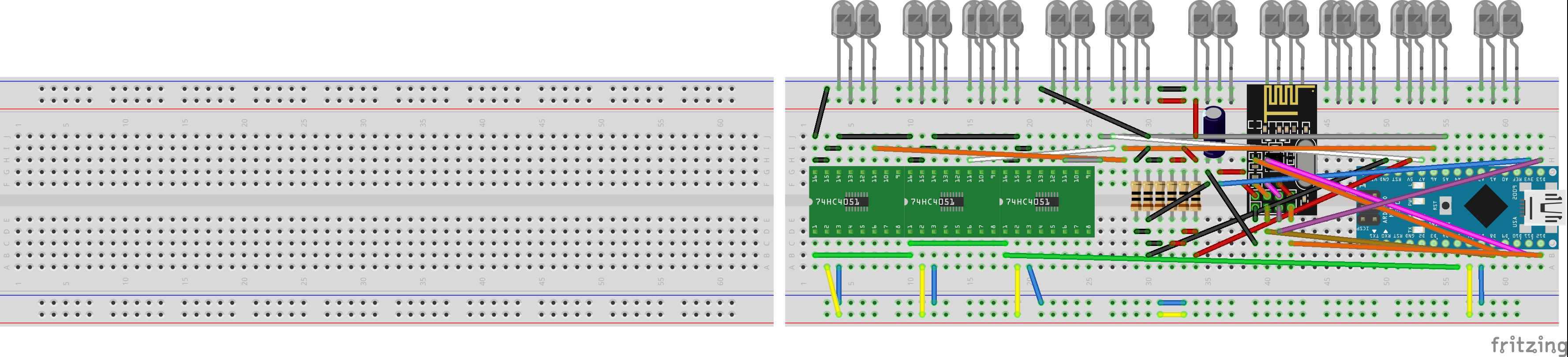
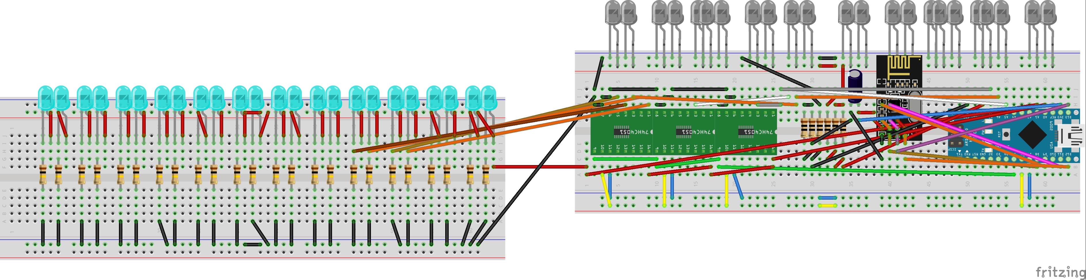
This is the first step in building the 4 primary hubs, they should all start out looking like this. The green ICs that are marked 74HC4051 represent the 4051 multiplexers, yours should look like completely black ICs, despite the difference in looks, the wiring is the same.
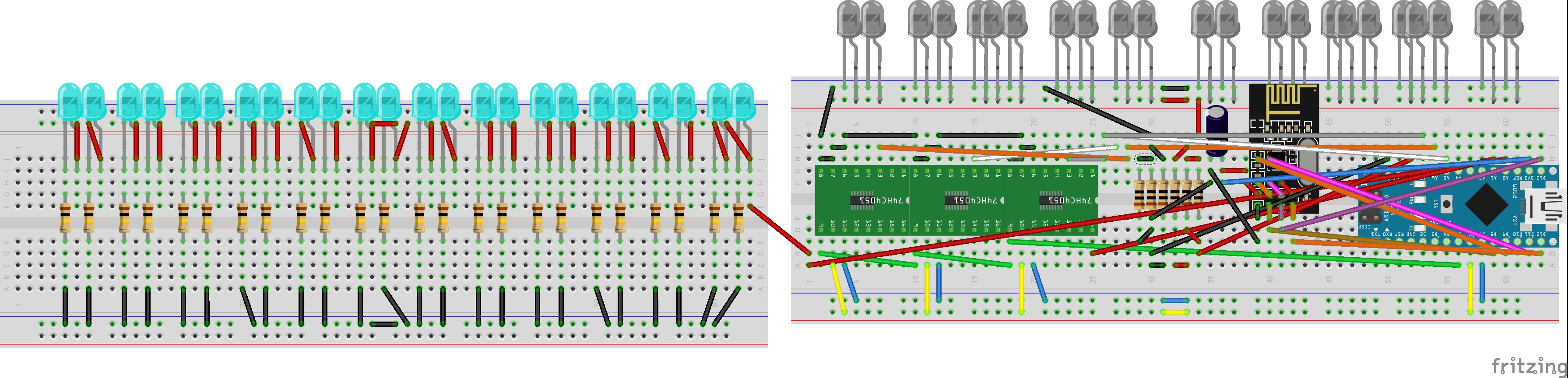
Step 2
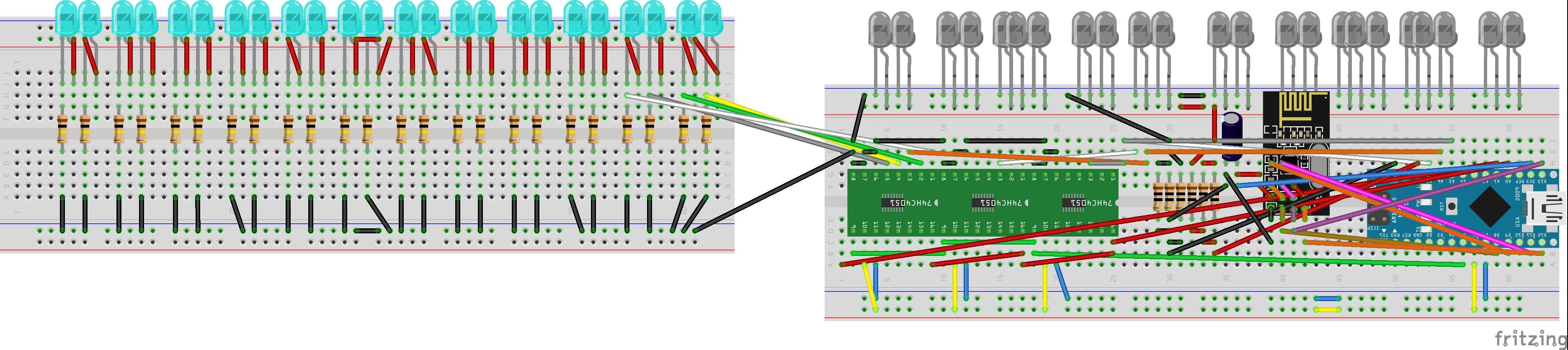
This is the second step to the 4 primary hubs, in this step we just add more components to the circuits for Hubs 1-4 we have started to make. At this point, all the Hubs are identical in the wiring.
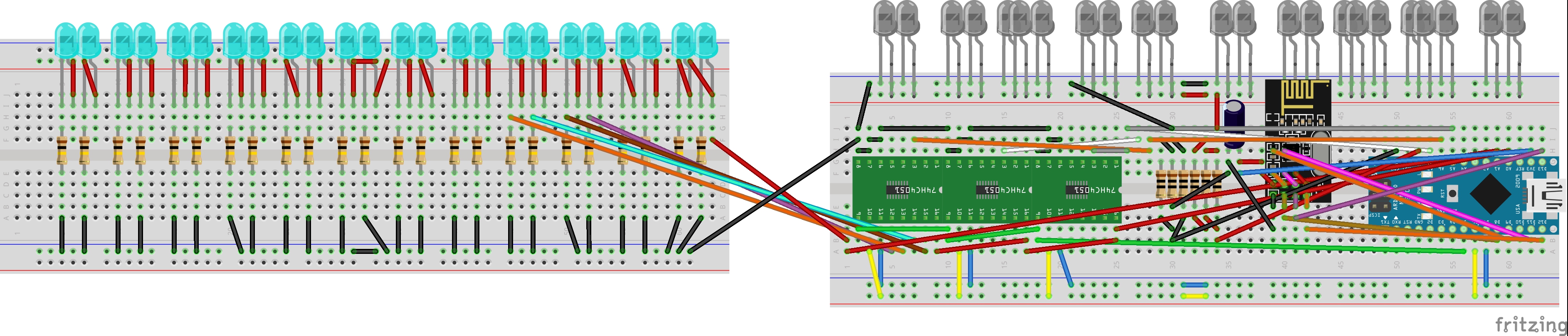
Step 3 (Hubs 1 & 3)
On this step, hubs 1&3 start to look different from 2&4, wiring the phototransistors to the multiplexers is different for hubs 1 &3 so please make sure you only make these adjustments for 2 of the 4 circuits you are working on. Those 2 circuits you make these adjustments to are now going to be referred to as 'Hubs 1 & 3'.
Step 3 (Hubs 2 & 4)
In the last step (step 3 (hubs 1 &3)) we made adjustments to hubs 1 & 3, now we have to make changes to Hubs 2 & 4 so that they are unique from 1 & 3. Take the remaining circuits (excluding 1 & 3) and make the following adjustments to them. Those 2 circuits you make these adjustments to are now going to be referred to as 'Hubs 2 & 4'.
Step 4 (Hubs 1 & 3)
In Step 3 (Hubs 1 & 3), we wired up half of a multiplexer with 4 phototransistors, now we are going to hook up another 4 for Hubs 1 & 3 each. Notice that the previous connections we made on Hubs 1 & 3 do not appear in this image, some connections were taken off so that you may clearly view the connections for the second set of 4 transistors. You should not remove the connections made for the first 4 phototransistors in step 3 (Hubs 1 & 3), merely add these connections to the hubs.
Step 4 (Hubs 2 & 4)
In Step 4 (Hubs 2 & 4), we wired up half of a multiplexer with 4 phototransistors, now we are going to hook up another 4 for Hubs 2 & 4 each. Notice that the previous connections we made on Hubs 2 & 4 do not appear in this image, some connections were taken off so that you may clearly view the connections for the second set of 4 transistors. You should not remove the connections made for the first 4 phototransistors in step 3 (Hubs 2 & 4), merely add these connections to the hubs.
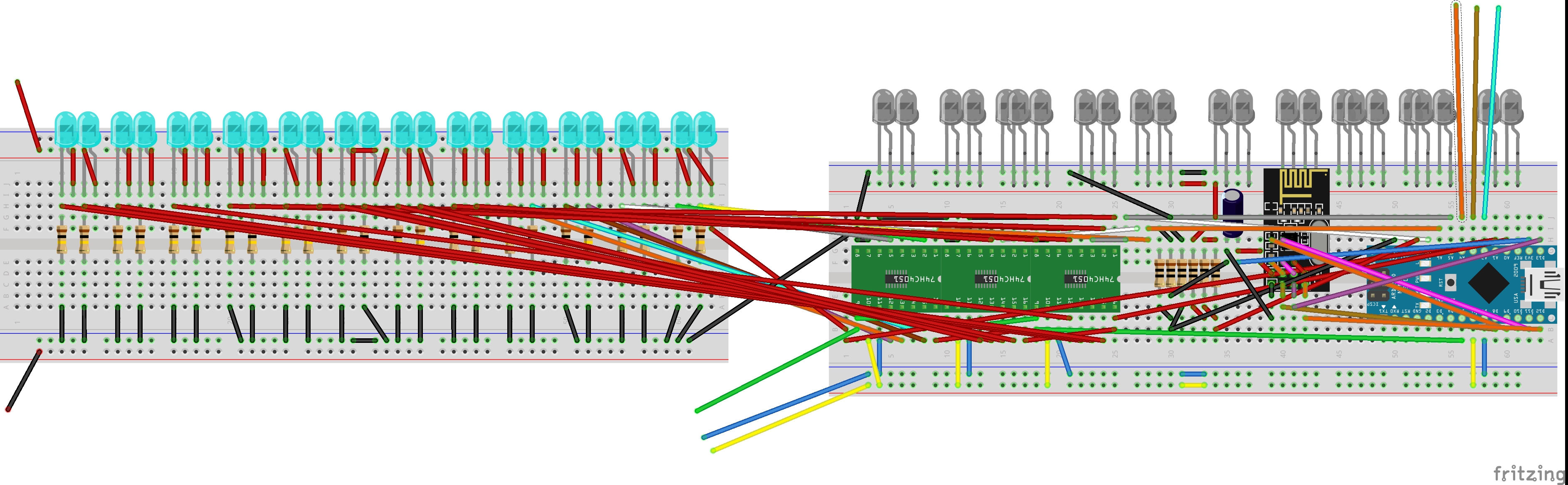
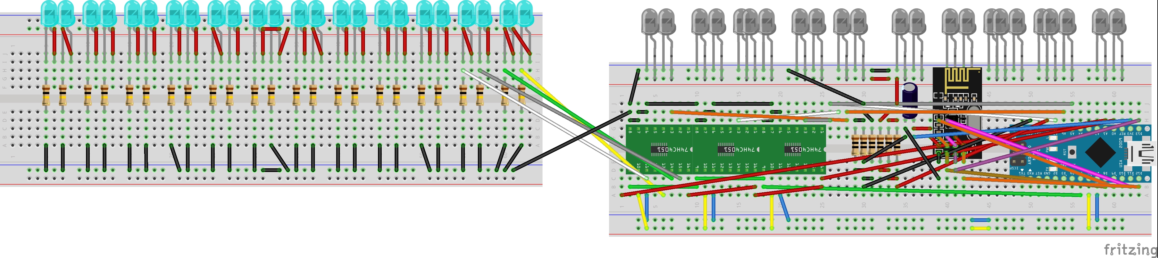
Step 5 (Hubs 1 & 3)
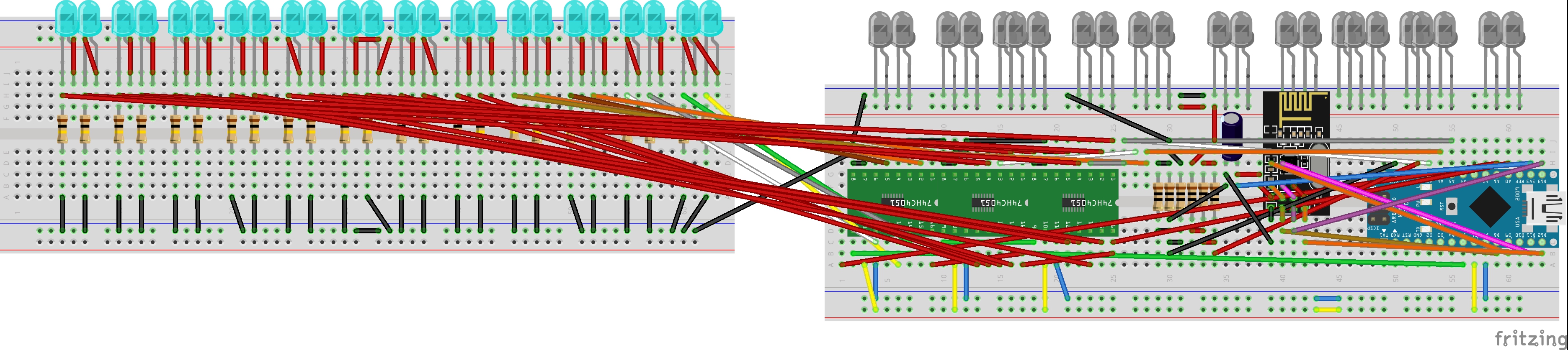
In step 4 (Hubs 1 & 3), we completed the connections for one multiplexer and 8 corresponding phototransistors. Now, we are going to connect the 3 remaining multiplexers to the 16 remaining phototransistors in the same fashion we hooked up the first 8 phototransistors to the first multiplexer. The image is crowded with wires, but this is to show how the finished product of all the multiplexers hooked up to the phototransistors should look like. If you cannot remember how to hook up the rest of the phototransistors, please refer back to step 3 (Hubs 1 & 3) and step 4 (Hubs 1 & 3).
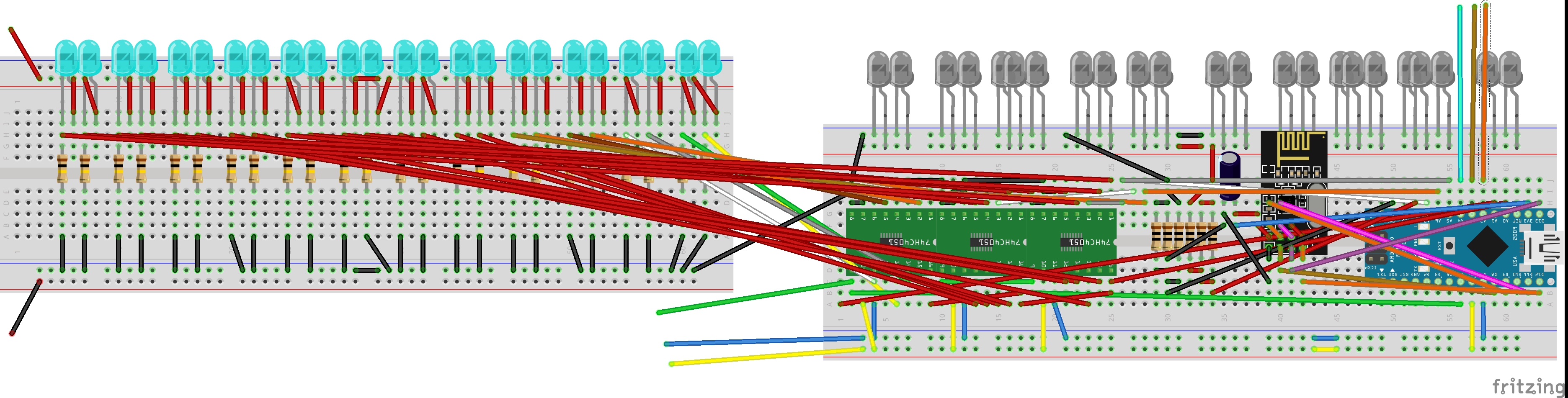
Step 5 (Hubs 2 & 4)
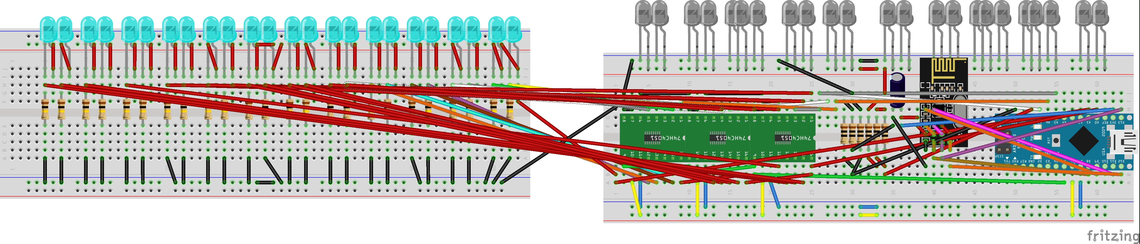
In step 4 (Hubs 2 & 4), we completed the connections for one multiplexer and 8 corresponding phototransistors. Now, we are going to connect the 3 remaining multiplexers to the 16 remaining phototransistors in the same fashion we hooked up the first 8 phototransistors to the first multiplexer. The image is crowded with wires, but this is to show how the finished product of all the multiplexers hooked up to the phototransistors should look like. If you cannot remember how to hook up the rest of the phototransistors, please refer back to step 3 (Hubs 2 & 4) and step 4 (Hubs 2 & 4).
Hub 1 Modular
In order to build a modular system, we need to make adjustments to Hub 1 (you can pick which one of Hub 1 and 3 is "1" because they should be identical at this point) so that it can accept more receiver hubs. In order to do this we extend some of the connections and leave the wires hanging off of the breadboard using male to female wires (the male end should be in contact with the breadboard and the female end should be hanging off of the breadboard). We do this for 8 connections as shown.
Hub 2 Modular
In order to build a modular system, we need to make adjustments to Hub 2 (you can pick which one of Hub 2 and 4 is "2" because they should be identical at this point) so that it can accept more receiver hubs. In order to do this, we extend some of the connections and leave the wires hanging off of the breadboard using male to female wires (the male end should be in contact with the breadboard and the female end should be hanging off of the breadboard). We do this for 8 connections as shown.
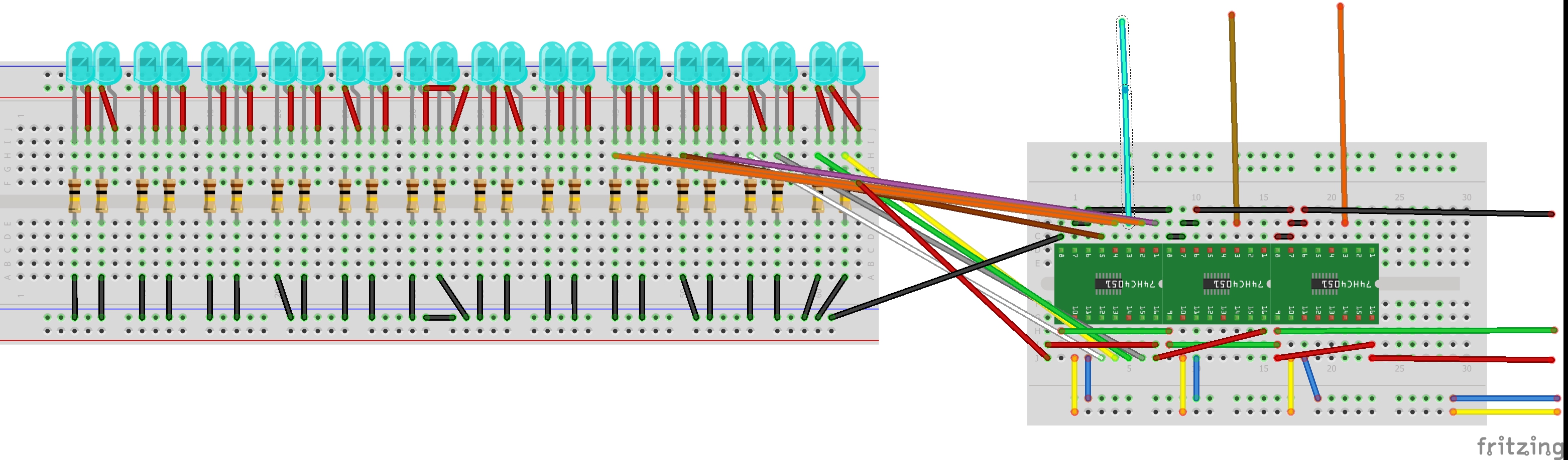
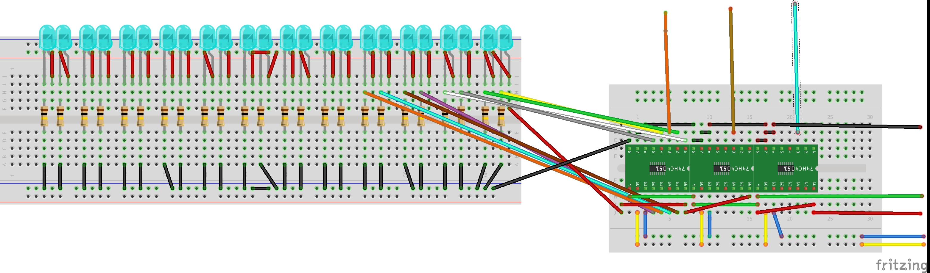
Receiver Extension Module (Hub 1)
Now that Hubs 1-4 are complete in wiring, we can create the extension receiver hubs that can attach to hubs 1 and 2 to increase the number of receivers on the system (effectively increasing the physical resolution of the system). We create an extension module with the multiplexers on the small breadboard. Complete the connections for the multiplexers to the phototransistors the same way you did for Hub 1 and its phototransistors and multiplexer connections.
Receiver Extension Module (Hub 2)
Now that Hubs 1-4 are complete in wiring, we can create the extension receiver hubs that can attach to hubs 1 and 2 to increase the number of receivers on the system (effectively increasing the physical resolution of the system). We create an extension module with the multiplexers on the small breadboard. Complete the connections for the multiplexers to the phototransistors the same way you did for Hub 2 and its phototransistors and multiplexer connections.
Emitter Extension Module (Hub 3 & 4)
We have created Hubs 1-4 and receiver extension modules for Hubs 1 and 2, now we need to create emitter extension modules for Hubs 3 & 4. The wiring for these modules is fairly straightforward, just make sure that you leave two wires hanging off of the two terminals as shown in the images. Create two of these circuits (for Hub 3 and 4) and ensure they each have the two wires so that they may attach to their respective hubs.
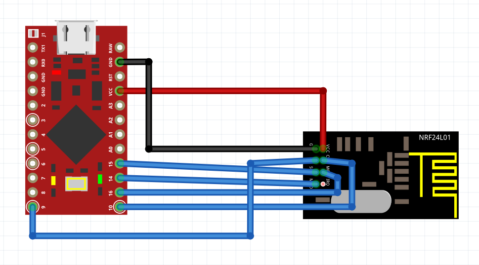
Hub 5
This is the wiring for Hub 5, it is the most straightforward as it is composed of the Pro Micro and the NRF24L01. You may use the female to female jumper wires to connect the two devices together.
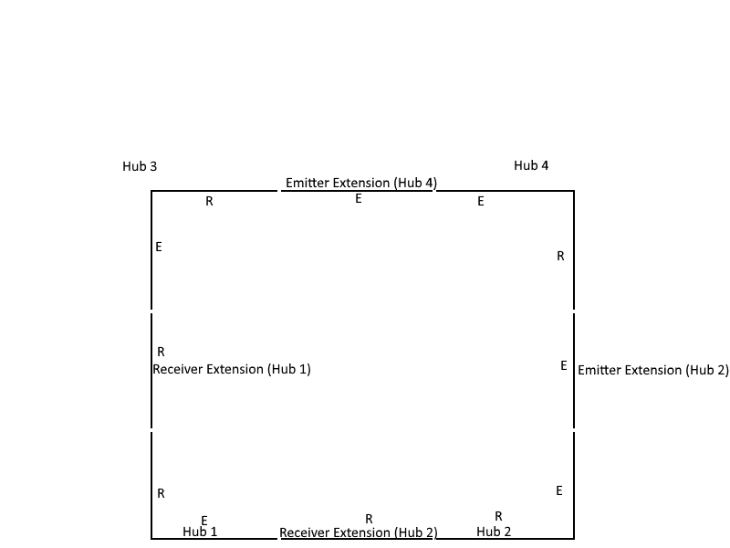
Hub and Extension Module Orientation
In order to orient the modules and the hubs correctly, I created a visual that shows how the different modules face each other. The modules are oriented with Hub 1 being in the bottom left, Hub 2 in the bottom right, Hub 3 at the top left, and Hub 4 at the top Right. Connect receiver extension modules to their respective Hubs via with the male headers coming off of the extension matching their female counterparts (visible through color coding of the diagrams) and the emitter extensions with their respective hubs in the orientation in the image (use the color coding again to determine how to connect the modules together).
Code
Hub 4
This is the code to be uploaded to the Arduino Nano controlling Hub 4.
Hub 2
This is the program to be uploaded to the Arduino Nano that is connected to hub 2.
Hub 1
This is the code to be uploaded to the Arduino Nano controlling Hub 1.
Hub 3
This is the code to be uploaded to the Arduino Nano controlling Hub 3.
Hub 5
This is the code to be uploaded to the Arduino Nano controlling Hub 5.


Comments