


Hardware components | ||||||
 |
| × | 1 | |||
| × | 1 | ||||
 |
| × | 1 | |||
 |
| × | 1 | |||
 |
| × | 1 | |||
 |
| × | 1 | |||
Software apps and online services | ||||||
 |
| |||||
 |
| |||||
Hand tools and fabrication machines | ||||||
 |
| |||||
Before the detailed documentation, I have attached my project: DriverBraking pattern Analyzerdemo and its feature in below YouTube link, Kindly watch it.Driver Braking Pattern AnalyzerProblem Statement:
- In a speed breaker, The driver may over brake which will reduce the vehicle's acceleration. Fuel Consumption will be more due to such activity.
- If the driver doesn't apply enough brake, it may affect the vehicle's suspension
- In a Electric vehicle, The above two pattern will impact the power consumptions
I have developed a TinyML model using Edge impulse software. This model can predict your braking skills in speed breakers and potholes. I have added external sensors over my brake pedal and accelerometer for data capturing. This model will classify your braking into :
- Good Braking
- Over Braked
- Under Braked
- Flat Road Drive
The complete architecture is mentioned in below diagram :
The Driver Braking Pattern Analyzer involves:
- Vehicle Data Simulation
- Model Training in Edge Impulse
- Classification
In this project, Instead of reading Vehicle's data from vehicle CAN bus. I have added external sensors and captured the real time values which will be similar to real vehicle data.
My approach is to make a independent module which can be fitted in any four wheelers and data can be captured in real time.
1.1Brake Pedal
In my Car, I have placed the Flex sensor4.5" under my brake pedal.
you can see the sensor placement in below picture.
Brake Pedal value calculation
For calculating the brake pedal pressed value calculation, I have used threshold method. In startup, I will press the brake pedal fully for 7 sec and then I release it for 7 seconds.
I have used secondary controller - Arduino Nano for calibration and calculating the brake pedal pressed value.
CircuitConnection
connect the flex sensor as per the below diagram and flash the below code.
//Flex Sensor - Brake pedal pressed value calculation
#include <Wire.h>
//Constants:
const int flexPin = A0; //pin A0 to read analog input
uint16_t FullbrakeUpperthreshold=0;
uint16_t FullbrakeLowerthreshold=0;
uint8_t brakepedalpressedVal=0;
float time_ms=0;
//Variables:
int FlexSensorvalue; //save analog value
float avgFlexValue=0;
boolean CalibrateFlexBrakepedalvalue=1;
int Linearinterpolation( float x , float x0, float x1, float y0, float y1);
void setup(){
Serial.begin(115200); //Begin serial communication
// Start the I2C Bus as Master
Wire.begin(1); //Begins I2C communication with Slave Address as 1 at pin (A4,A5)
Wire.onRequest(requestEvent); //Function call when Master request value from Slave
}
void loop(){
if(CalibrateFlexBrakepedalvalue==1)
{
delay(5000);
Serial.println("Press Full Brake pedal for 7 seconds"); //Print
for(int i =0 ; i<50;i++)
{
FlexSensorvalue = analogRead(flexPin); //Read and save analog value from potentiometer
avgFlexValue=FlexSensorvalue+avgFlexValue;
Serial.println(FlexSensorvalue); //Print value
delay(100);
}
FullbrakeUpperthreshold=avgFlexValue/50;
avgFlexValue=0;
Serial.print("FullbrakeUpperthreshold : ");
Serial.print("\t");
Serial.println(FullbrakeUpperthreshold);
Serial.println("Release Brake pedal for 7 seconds"); //Print
delay(5000);
for(int i =0 ; i<50;i++)
{
FlexSensorvalue = analogRead(flexPin); //Read and save analog value from potentiometer
avgFlexValue=FlexSensorvalue+avgFlexValue;
Serial.println(FlexSensorvalue); //Print value
delay(100);
}
FullbrakeLowerthreshold=avgFlexValue/50;
avgFlexValue=0;
Serial.print("FullbrakeLowerthreshold : ");
Serial.print("\t");
Serial.println(FullbrakeLowerthreshold);
CalibrateFlexBrakepedalvalue=0;
delay(10000);
}
delay(1); //Small delay
}
// Linear interpolation formula to calculate brake pedal value
int Linearinterpolation( float x , float x0, float x1, float y0, float y1)
{
int y=0;
y= y0+(((x-x0)*(y1-y0))/(x1-x0));
return y;
}
void requestEvent() //This Function is called when Master wants value from slave
{
FlexSensorvalue = analogRead(flexPin); //Read and save analog value
// Bringing to threshold value
if(FlexSensorvalue<FullbrakeUpperthreshold)
{
FlexSensorvalue=FullbrakeUpperthreshold;
}
else if(FlexSensorvalue>FullbrakeLowerthreshold)
{
FlexSensorvalue=FullbrakeLowerthreshold;
}
brakepedalpressedVal=Linearinterpolation(FlexSensorvalue,FullbrakeUpperthreshold,FullbrakeLowerthreshold,100,0);
Serial.println(brakepedalpressedVal); //Print value
Wire.write(brakepedalpressedVal); // sends one byte converted POT value to master
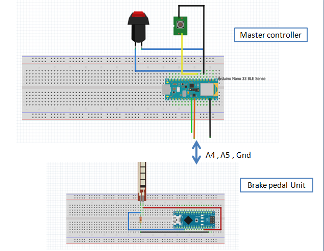
}Connect the A4, A5 of Arduino Nano to the master controller "ArduinoNano33 BLESense". The brake pedal device will act as slave in I2C and the master "ArduinoNano33 BLESense" will request and get the brake pedal pressed data from slave device.
1.2 Z-Axis Accelerometer data of Vehicle
I have placed the Arduino Nano 33 ble sense on top of the dashboard in my car.
The Nano 33 ble sense has inbuilt accelerometer. I have used that value as vehicle Z-Axis data.
1.3 Vehicle Speed simulation
For a speed simulation, I have attached the push button on top of the gear and whenever I press the brake pedal, I will press the push button also, which will reduce the speed by calibrated factor. The algorithm will work like in below chart.
I derived at calibration factor based on when I press the push button, the speed from 25kmph will be reduced to zero in 4 seconds.
To reset the vehicle speed, I have added the below algorithm in Nano 33 Ble sense.
Follow the steps in the below link for connecting the Arduino Nano BLE 33 Sense to the Edge Impulse
https://docs.edgeimpulse.com/docs/arduino-nano-33-ble-sense
Go to command prompt and type below command
$ edge-impulse-data-forwarderAnd select the Arduino connected COM port. After connecting, you can give your edge impulse login credentials and select your project.
I have collected 22mins of data for different braking pattern.
Good Braking- Data
Here is the collected data sample for good braking.
In above graph, we can notice the drop in vehicle speed and good braking applied.
Over Braked - Data:
When you press full brake in a speed breaker, it could make your vehicle stop or almost near to zero. From the above data graph, you could notice the vehicle speed dropping down to zero and full brake applied after zero speed to avoid the vehicle running back from speed breaker.
Under Braked - Data :
NormalFlat Road Drive - Data:
In a normal flat road, Vehicle will be maintaining at constant speed and driving will be in a flat surface, not any potholes or speed breakers.
After data acquisition, I have configured the impulse as below configuration.
Set you filtering techniques as None, Since the full brake might show as zero in filtering.
NN classifier settings
The model training output
Based on the data and model training configuration, I have achieved 94.5% in training.
Hardware:Circuit connection:
Brake Pedal value - Circuit connection of flex sensor with Arduino Nano
The connection between Arduino Nano 33 ble sense and brake pedal unit is described in below connection diagram.
Here the glimpse of sensor placements and Controller placement inside my car.
Using this TinyML model, We can able to predict the driver braking pattern more accurately.
Learnings:
One of the great learnings from this project was how to capture the vehicle data without interfering with CAN vehicle bus and I have approached with different alternative sensors like flex sensors, Placing Accelerometer on top of dashboard and speed simulation mechanism.
And there was more challenges while capturing real time data in driving !
Thank you ! Hope this project gives you some insight about TinyML in automotive field. Wish you all the best ! Innovate for better future :)


Comments
Please log in or sign up to comment.