


Hardware components | ||||||
| × | 1 | ||||
Software apps and online services | ||||||
 |
| |||||
| ||||||
Hand tools and fabrication machines | ||||||
 |
| |||||
I built this 3D printing lamp with red and yellow LEDs to simulate a flickering candle. The name of the project is "Chubosphera" because I have been inspired by italian artist A.Mendini that made his famous Cubosfera lamp, I love it.
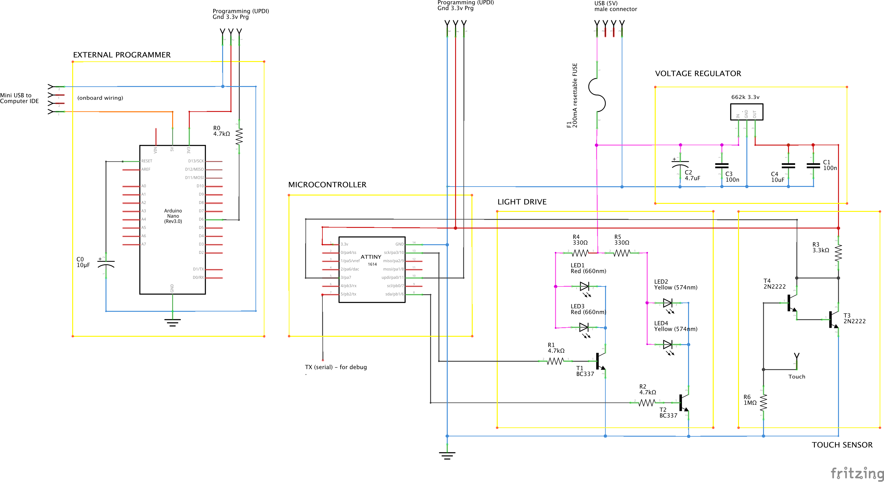
The Circuit and the Software:The MCU works at 3.3v so I put a voltage regulator at the beginning of the circuit to lower down the 5.0V of the USB power. In reality the LED are driven at 5.0V outside the regulator. There is a resettable fuse too: in case of short circuit you must disconnect the USB cable and wait a few minutes it cools down and reactivates itself to normal functionality. The power is provided by the USB cable: ones passed through the 3D printed bottom item you may cut the unnecessary white and green wires for data, keep just the red and black ones for 5Vcc power (+) and (-).
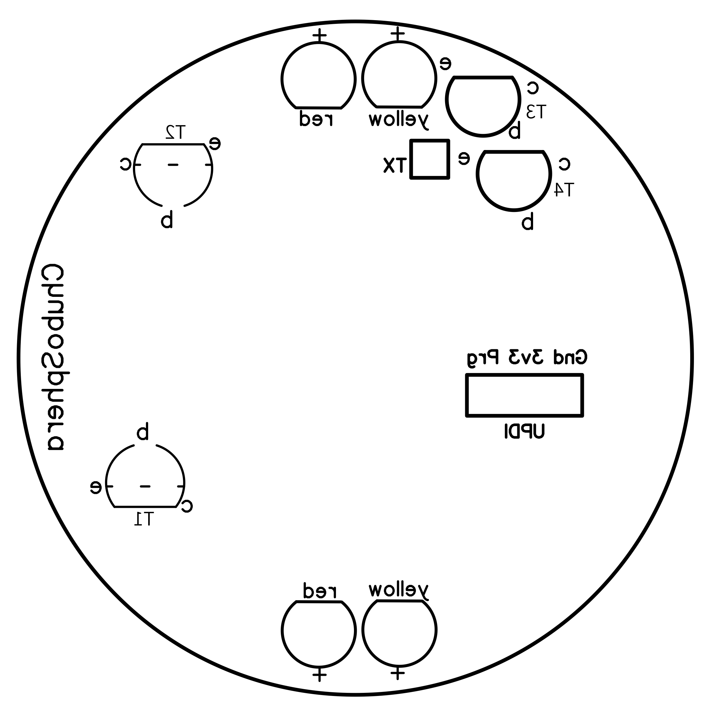
The LED flickering is made by an ATtiny1614 microcontroller: it generates random numbers to drive two transistors and LEDs with PWM. Other two transistors are set in darlington configuration for sensing the touch of the wire on top of the lamp and inform the MCU that provide to switch the LEDs on/off. In case the touch sensing is too sensitive, so it occasionally switch on by itself without touching, or just approaching a finger/hand, I suggest to install the resistor of 1M Ohm between the sensing wire (base "b" of T4) and GND. This phenomenon could happen because of static electricity or EMF/RF noises, light-switch spikes, or ghosts... :-) present in the air of your room captured by the sensing wire. Otherwise is not necessary to install the 1M Ohm resistor.
If you prefer to have a mini tactile push button instead of the touching wire, just install one connecting both 2 wires of the relative connector, and install the 1M Ohm resistor.
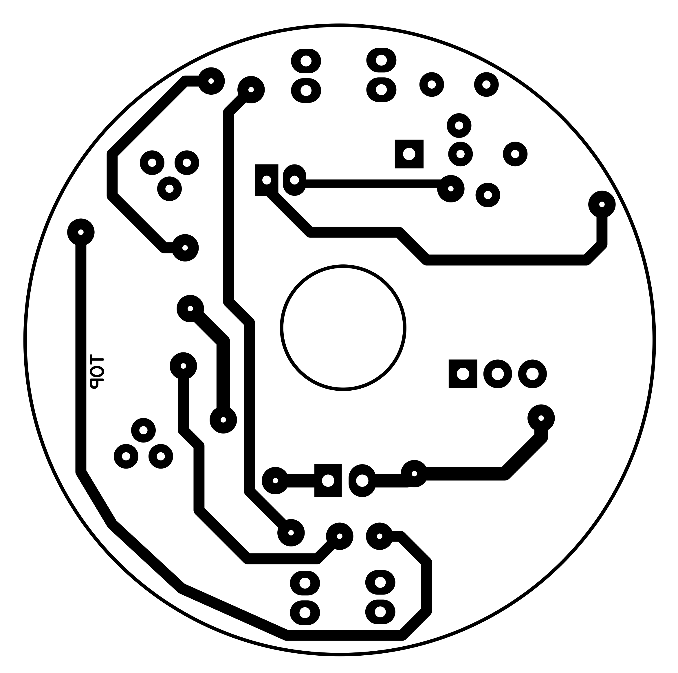
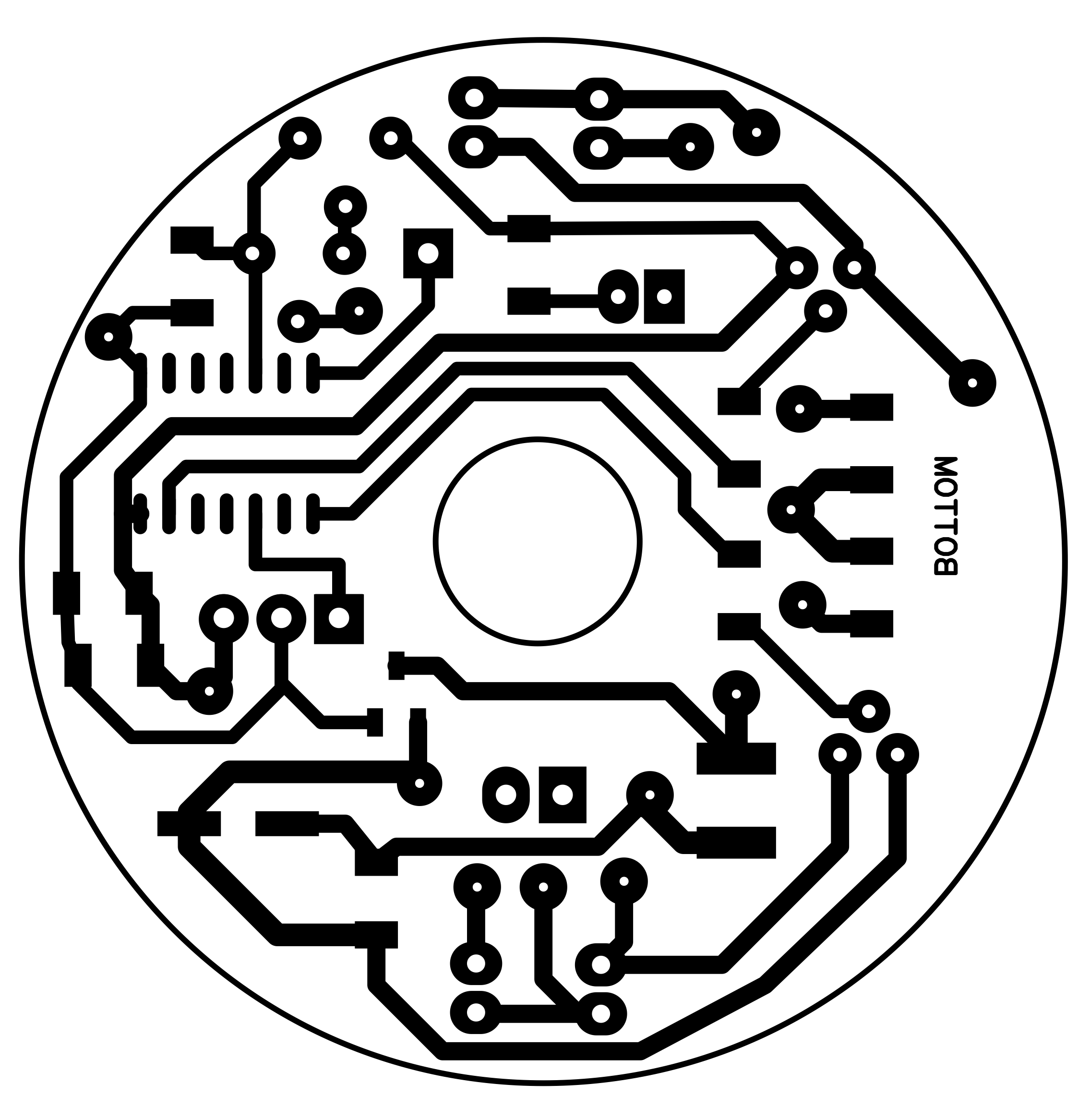
PCB and 3D printing:The material I used for prototyping the Chubosphera is normal semi transparent PLA with 10% of infill, enough transparent to let light make its candle effect well in the dark. For a good effect you could use other materials as per resin (transparent or translucent), or polycarbonate (translucent)... let me know if you try one of these and how has been the final result.
To have a full lamp you need to print two times the Chubo 3D file and put them together; to keep them as one piece you have to put on two of the corners a couple of neodimio 6x3mm magnets (watch the correct side of every magnets!). I made room for the magnets, they should enter in place with a bit amount of force, or glue them if not. The size of the PCB is 46x46mm but the final shape it will be circular (diameter 46mm) with a hole in the middle (diameter 9mm); you have to place the PCB between the two "towers" that are pointing to each other, there is a gap for it. I made also two 3D additional items (see picture below): the one on top, red in the picture, is for placing the touch sensing wire (or a mini tactile push button) and let circulate the air through 4 small holes; the one on bottom, blue in the picture, is for passing the USB cable and the air as well.
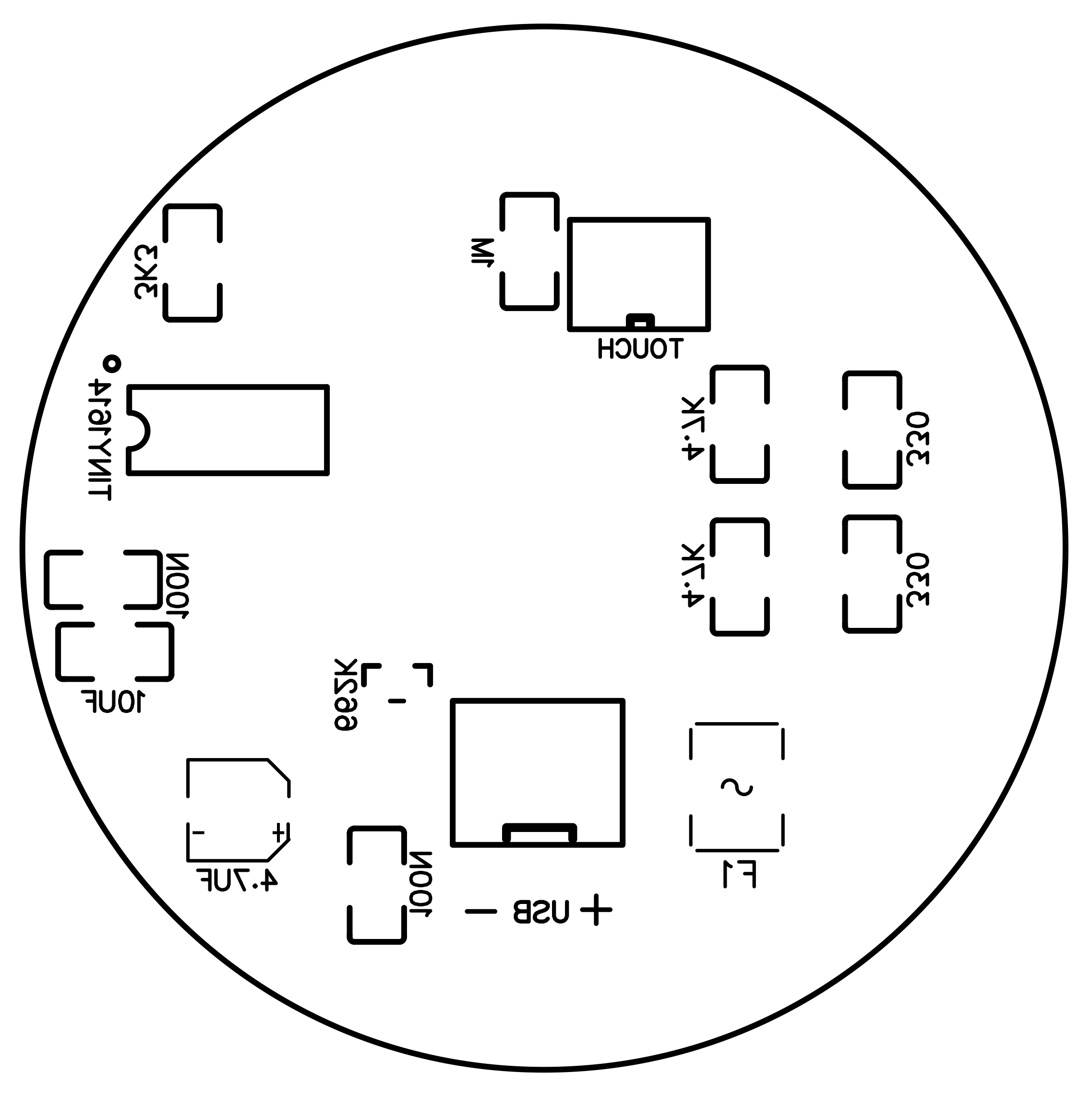
- ATtiny 1614 microcontroller (SMD)
- 662k 3.3v voltage regulator (SMD)
- 2 x 5mm red LED
- 2 x 5mm yellow LED
- 2 x BC337 transistors
- 2 x 2N2222 transistors
- 15 x copper 0.8mm rivets (to pass through PCB board)
- 4.7uF electrolytic capacitor (SMD)
- 10uF capacitor (SMD)
- 2 x 100nF capacitor (SMD)
- 200mA resettable fuse (SMD)
- 2 x 330 Ohm resistor (SMD)
- 2 x 4.7k Ohm resistor (SMD)
- 3k3 Ohm resistor (SMD)
- 1M Ohm resistor (SMD) - optional, see notes
- 46x46mm double face fiberglass PCB board (to shape round)
- USB-A cable 3.4mm diameter max
- A piece of solid wire for touch sensing (or a mini tactile push button)
- 4 x auto-adhesive transparent rubber feet
- JST-HX 2.5mm connector (male and female) 2 pins for USB power
- JST-PH 2mm connector, male and female, 2 pins (used 1 for touching wire, both 2 for tactile mini push button)
- 4 x 6x3mm mini neodimio magnets
A couple of years ago I read this John Bradnam's ATtiny 1614 Project so I bought a couple of these microcontrollers to take a new way and enjoy a new adventure, then I made MyTiny first testing circuit. Everything has worked on my choice to power it at 3.3v. Up to today I tested and verified: digitalRead, digitalWrite, analogRead, analogWrite both PWM and DAC; I provided a serial monitor through pins RX/TX <-> FTDI serial interface and SoftwareSerial library; finally I connected an OLED 128x32 display by the way of SDA/SCL and Wire library. Cool!
To program the ATtiny by the way of anArduino NANO and IDE please read Bradnam's instructions at above link. Here some of it (I provided 3 pins on the board named UPDI for this purpose):
- install jtag2updi sketch into Nano
- connect a 10uF 25V electrolytic capacitor on Nano between RST (+) and GND (-)
- connect a 4.7K resistor and a wire from Nano pin D6 to ATTINY pin UPDI (pin 10)
- connect GND pin from Nano to ATTINY GND (pin 14)
- connect +3.3V pin from Nano to ATTINY VCC (pin 1)
- keep connected Nano and Arduino IDE
- on IDE change programmer to "jtag2updi"
- on IDE change board to "ATtiny1614..."
- on IDE change other parameters as per attiny-setup.jpg screenshot (see below)
- on IDE compile the sketch to install on ATTINY
- on IDE Upload the sketch to ATTINY (by the way of Nano still connected)
- the ATTINY should run with the installed sketch
- you may disconnect ATTINY from Nano...
If you like to see datas similarly the one on Arduino IDE serial monitor for debugging, you have to set at the beginning of the code "boolean isDebug=true;"; additionally you have to connect your computer to a Serial-to-USB converter (i.e. a FTDI board RX port) to microcontroller TX port, I provided a pin "TX" for this, together with a software serial communication like CoolTerm, set at 115200 baud, installed on your computer.
Some real pictures:Even this time I decided to try the famous and popular PCBWay services. Some our beautiful project deserve a real professional service giving to them precise and superb items like PCB and 3D enclosure/component. I visited for the first time PCBWay website some months ago (http://www.pcbway.com) and after a few minutes I had been able to obtain the final price of the PCB just uploading the.ZIP Gerber file and setting some preferences of the board like colour: I choosen the white but is still available the most popular green, or a shining blue or red or others. They shown to me a preview of the board: impressive.
The same for the 3D printings (just uploading the.STEP or .STLfile/s) and you cannot image how many materials are available: PLA, ABS, PETG, Resin, Polycarbonate but as well as Aluminium or Steel or... Titanium! What, Titanium?! It is incredible.
They offer other services that actually I have not tried them yet but with these two I can say I am very satisfied. Shipping time were quick. The price was adequate. The customer care office and technician production office demonstrated to me to be ready and "sharp" for details.
11.03.2025 - the 3D printing files are available on my account at grabcad.com website too;
13.03.2025 - In case the touch sensing is too sensitive, so it occasionally switch on by itself without touching, or just approaching a finger/hand, I suggest to install the resistor of 1M Ohm between the sensing wire (base "b" of T4) and GND. This phenomenon could happen because of static electricity or EMF/RF noises, light-switch spikes, or ghosts... :-), present in the air of your room captured by the sensing wire. Otherwise is not necessary to install the 1M Ohm resistor.
If you prefer to have a mini tactile push button instead of the touching wire, just install one connecting both 2 wires of the relative connector, and install the 1M Ohm resistor.
01.04.2025 - If you wish I have a few PCB from PCBWay ready to solder the components on, I can send to you one if still available: first come first served.


Comments