

Hardware components | ||||||
 |
| × | 1 | |||
| × | 1 | ||||
| × | 1 | ||||
Home automation systems monitor and/or control home appliances such as lighting, climate, entertainment systems, and other devices. This also includes home security such as access control and alarm systems. For switching and controlling these systems one often requires a relay based mechanism that enables the switching of large amounts of current.
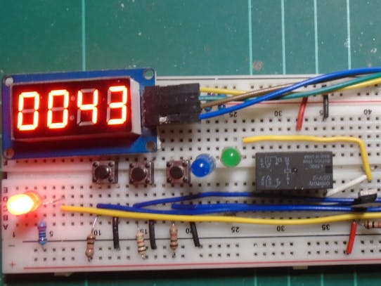
This project features an Arduino Nano controlled timer which will count down from a preset time. When the timer reaches zero, the Nano activates a relay switch. The relay can be connected to two external devices for control. Buttons are provided to adjust the timeout period as well as an on/off button to start and stop the timer.
ComponentsA TM1637 7 segment LED timer module provides the timer display in minutes and seconds. (Hours and minutes are available via a separate sketch) These modules are available for very little money from Ebay and Ali Express.
The relay is a double pole, double throw (DPDT) Omron G5V-2 relay which cost around $1.00 each; also from Ebay and Ali Express.
There are three tactile buttons: a button to adjust the minutes, one to adjust the seconds and a third to start, or stop the timer. Stopping the timer also switches off the relay if it has been activated.
Finally, an Arduino Nano performs the actual timer and relay switching logic. A single 2N2222 transistor is used by the Nano to do the actual switching of the relay because it is doubtful that a pin on the Arduino can supply enough current to energize a relay coil.
HowTheCircuitWorks
The brains of the circuit is provided by the Arduino Nano which handles the timer countdown and relay activation functions. An explanation of how the code works that runs on the Nano follows in the next section. The buttons are used to set the timeout period and start and stop the timer respectively; these are connected to the Nano's digital pins. When the timer reaches zero, the Nano sends a logic HIGH signal through digital pin 6. This pin is connected to the gate of a 2N2222 transistor, which switches on in response to the HIGH signal from the Nano. This in turn energizes the coil of the relay which switches on Output B and switches off Output A.
Why two output control lines? Output A (pin 6 of the relay) turns off when the timer expires and Output B (pin 8 of the relay) turns on when the timer expires. Having one output turn on and the other turn off when the timer expires can be useful under some circumstances, but if you only need to turn on, or turn off a device then simply leave one of the outputs unconnected. For demonstration purposes I have the outputs connected to LEDs.
Pin 4 of the relay is the positive supply voltage for the devices connected to the output pins A and B. I have this tied to 5 Volts in the circuit above so I can drive a couple of LEDs, but if your devices need a higher voltage than this, then supply that voltage on pin 4.
You may have noticed the diode connected across the contacts to the relay's coil. This is necessary to prevent a voltage spike potentially damaging the transistor which can happen when the relay is turned on and then off. When you switch off the current to an electromagnet, the electric field surrounding the coil collapses. As it does so it sends a reverse voltage spike down the coils power connections. The diode absorbs the energy stored in the relay's coil when you switch the current off. Without the diode, the energy will cause a large and probably destructive voltage spike which would likely destroy the transistor.

Comments