


Hardware components | ||||||
 |
| × | 1 | |||
_ztBMuBhMHo.jpg?auto=compress%2Cformat&w=48&h=48&fit=fill&bg=ffffff) |
| × | 1 | |||
 |
| × | 1 | |||
 |
| × | 1 | |||
 |
| × | 1 | |||
 |
| × | 1 | |||
 |
| × | 1 | |||
 |
| × | 1 | |||
 |
| × | 1 | |||
 |
| × | 1 | |||
Software apps and online services | ||||||
 |
| |||||
 |
| |||||
Hand tools and fabrication machines | ||||||
 |
| |||||
This tutorial will explain how to build an open source machine for biofeedback. But first a bit of theory.
What is biofeedback?
[Font: Wikipedia | https://en.wikipedia.org/wiki/Biofeedback]
Biofeedback is the process of gaining greater awareness of many physiological functions primarily using instruments that provide information on the activity of those same systems, with a goal of being able to manipulate them at will. Some of the processes that can be controlled include brainwaves, muscle tone, skin conductance, heart rate and pain perception. Biofeedback may be used to improve health, performance, and the physiological changes that often occur in conjunction with changes to thoughts, emotions, and behavior.
The SponsorELEGOO
This project is sponsored byELEGOO (https://www.elegoo.com).Elegoo implies the combination of open-source electronics and structures that creates everything. You can use the 37 in 1 sensor kit module to create this project and expand the possibility of the machine by using more and more sensors. This is the link of the product on the ELEGOO official site.Buy the kit on Amazon. Use this link to apply a little discount https://amzn.to/3kUeajB
Let's start with the list of materials needed:
- Arduino / Genuino UNO (https://amzn.to/3f5X6WQ)
- Breadboard (http://amzn.to/2fitZAD)
- 5V LCD 16 char (https://amzn.to/3kBpDo3)
- Temperature sensor TMP36 (https://amzn.to/38OPIOu)
- 220k Ohm resistor (https://amzn.to/3nGxcfp)
- Trimmer for the LCD contrast (https://amzn.to/35wN3Xw)
- Two plates of copper or conductive metal (https://amzn.to/3nu9SBj)
- Some jumper connection cables (https://amzn.to/2IG6VyO)
Elegoo Kit
ELEGOO Upgraded 37 in 1 Sensor Modules Kit with Tutorial Compatible with Arduino UNO R3,MEGA2560,Arduino Nano. 100% compatible with Arduino official IDE, Raspberry Pi, and Nucleo STM32.
In this kit by ELEGOO you can find many components:
- 5V LCD screen 16 char
- DS18B20 Temp sensor
- DHT-11 Temp/Humi sensor
- 220k Ohm Resistor
- Trimmer for the LCD (resistor)
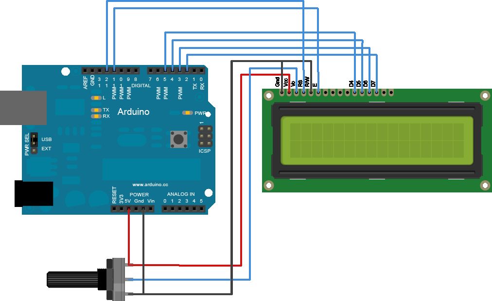
First we begin to build the electronic circuit on breaboard. We put all the components starting from the LCD.
We pay attention to where we insert the display on the breadboard.
This kind of LCD work on 5V with 16 columns and 2 rows. You can also use this module with keypad (https://amzn.to/3kBpDo3).
Follow the image to link the 10 pin to VCC, GROUND, POTENTIOMETER/RESISTOR and 6 Arduino pin.
When you have connected the LCD to the Arduino board try to this LCD Example sketch and see the result. Go to https://github.com/masteruan/Arduino-Biofeedback/blob/master/LCD_test and download the sketch.
Mount SensorsOk now you can mount the sensors. The TMP36 have 3 pin. Two for alimentation VCC and GND, and une for measurement. You can put the VCC pin and GND pin on the breadboard's VCC-GND pin. After put the measurement pin on the Arduino's A1 pin.
Sensors in the ELEGOO kit
In the ELEGOO kit you can find DS18B20 temp sensor. You can connect the sensor to the board by using the following pin.
G = GroundR = +5vY = Analog signal
Another temp sensor is the fantastic DHT-11 Humidity/temp sensor.
You can use this sensor to monitor the environment. In this way you can have two temp measures. The first one is the temp for the body the second one, DHT-11 monitor the environment temperature. Also you can calculate the "absolute temp" subtracting the environment temp to the body temp.
In the ELEGOO kit you can find DHT-11 temp/humi sensor. You can connect the sensor to the board by using the following pin.
S = Analog output pin
+ = +5v
- = GND
In this case you have to use the DHT library. It's available in the Arduino IDE. Follow the official guideline for the libraries and find "DHR sensor library" in the official Arduino libraries.
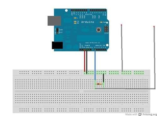
GSR sensorAfter this mounting you can create a GSR sensor. You can use two copper pieces. If you live in Europe, you can use the 1 or 2 euro money like in figure.
Put the pin of the copper pieces like in figure. Use a 220k Ohm resistor between GND and A0 Arduino pin.
Upload the sketchDouble check that everything is ok in the electronic circuit. Check especially the pins VCC and GND. Check that they are not reversed. Take your time for this control. The risk is to burn Arduino and electronic components used. When you finish this stage you just have to upload the sketch on the Arduino board. Click the link: https://github.com/masteruan/Arduino-Biofeedback/blob/master/Biofeedback. Go Upload!
Operating instructionsWhen away from the Arduino biofeedback appear on the screen you'll see the welcome screen. Keep your fingers between the temperature sensor TMP36 and supports the index finger and ring finger on the copper pieces. And then you can see how the device will begin to measure your vital signs like temperature and heart skin conductance.
On the screen you can read the current GSR temperature value, the maximum value GSR skin conductance and the time elapsed since the machine.
You can open the serial port of your computer and read the value on the screen. After 1 second the value are updated. You can create the report of entire measurement session. Like in photo.
Processing softwareAlso on Arduino Biofeedback Github repository https://github.com/masteruan/Arduino-Biofeedback you can find a Processing sketch for use a Processing graphical interface. View the GSR view value on the X Y diagram.
Future upgradeA good idea is try to use the ELEGOO NTC-MF52 3950 digital temperature sensor.
A0 = Analog signal output pin
G = Ground
+ = Vcc(reference voltage :5V DC)
D0 = Digital signal output pin
GSR sensor with Arduino UNO


Comments
Please log in or sign up to comment.