

Hardware components | ||||||
_wzec989qrF.jpg?auto=compress%2Cformat&w=48&h=48&fit=fill&bg=ffffff) |
| × | 1 | |||
Software apps and online services | ||||||
 |
| |||||
In part one we built a model of the Sharp IR sensor and learned how it works. We also implemented a software model to use range measurements on the Arduino. In this part we are going to add an Arduino block that can call an interrupt service routine (ISR) when triggered by one of Arduinos digital inputs.
Interrupts are useful in some cases as they can respond to particular hardware events without having code that constantly checks the status of an input, thus reducing the load on the processor. It can also be useful when the processor has to respond quickly to an event. Here we are going to use the interrupt to respond to an event that occurs when an object comes too close to the IR sensor. In the next section we will use it as an alert signal when a robot gets to close to something. The robot can then choose to back off, turn or just stop for example.
The focus here will be on how to use the interrupt block but comments about how it works is included to better understand it and in case someone would like to modify it or continue development.
Project FilesTo use the library, unzip the file after downloading the submission. Go to the blocks folder with MATLAB and type mex arduino_interrupt.c. This will compile the block for your Simulink installation. If the compilation fails, please check that you have selected a compiler with mex -setup.
- Read part 1 to get the background to the sensor model
- We recommend completing Getting Started with Arduino Mega 2560 Hardware
Same as part 1:
- Arduino Mega 2506 board
- Small breadboard with wires
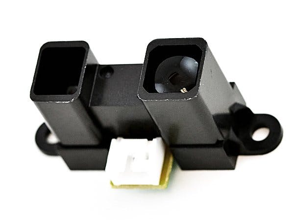
- 1 Sharp IR Sensor GP2Y0A02YK0F
- 1 Capacitor 10uF – 100 uF
- 1 Capacitor 1 uF
- 1 Capacitor 200 nF
- 1 Resistor 10 ohm
New components for part 2
- 1 LM311N Comparator
- 2 10k ohm resistors
- 1 10k ohm potentiometer
The arduino documentation includes a good overview and recommendations of how to use interrupts. There is also a table that maps different interrupt numbers to connection pins, for different boards, that you will need to consult when using interrupts pn your own project.
In this part we are going to use interrupt 0 which is connected to digital pin 2 on the arduino mega 2560 board. When an interrupt is triggered an interrupt service routine is called. An interrupt can be triggered when the voltage on the corresponding pin falls from high to low (falling) or when going from low to high (rising). There are two more trigger modes for the arduino mega, low and change. Please consult the documentation for more details.
To use an interrupt you must attach an interrupt service routine to an interrupt. This is what the new block will do. Since the interrupt service routine will interrupt other code it is generally recommended to do as little as possible in it. It is often better to just signal the main loop about an event and let it handle it than to do complex computations in the service routine.
The Simulink library and filesLet’s take a look at the new block. Download the zip-file[link] and unzip it in a folder. In MATLAB go to the folder and run the setup.m file then type MyArduinoLib. This library should open:
The block in the library can be used to map a hardware interrupt to a subsystem that will be executed as an interrupt service routine. The block has one input port, called simIRQ. This input port can be used in simulation to simulate a hardware interrupt. For execution on target it has no function. The output port is a function call signal. It should be connected to a function called subsystem as shown in task 2 below.
If you double click on the block to open the mask it includes four settings. Interrupt number and pin number are board settings and they must match the board according to the documentation. Mode decides what event on the input pin that will trigger an interrupt, rising, falling, change or low. The final setting enables and disables the input port.
For the interested, here is a short description of the files in the blocks folder that belongs to the library with the new block.
- MyArduinoLib.slx – The library file
- slblocks.m – a MATLAB file that describes the library. If this file is present the library will be included in the Simulink library browser.
- arduino_interrupt.c – This is a c-file s-function used to implement what this block will do during simulation. This file is compiled with: mex arduino_interrup.c (run mex -setup before). This has to be done before you use the library.
- arduino_int_lib.tlc – This file tells the code generator what kind of code to generate for this block.
- arduino_interrupt.tlc – Unsed by the file above to include a system header.
If you are interested, study the implementations of arduino_interrupt.c and arduino_interrupt.tlc to understand what they do. You can also change the behaviour if you like.
Task 1 – Modify the plant model and add a Schmitt triggerTo make simulations run faster than in the article 1, we will use a smaller plant model here than in the previous article. But please go back to the more detailed plant and test with it too to make sure the reduced model is enough. It is good Model-Based Design practice to make the system model before any hardware is built. This means that the idea or concept is tested with simulation before time and money is spent on hardware.
The new full system model is named system_model.slx and is shown below.
As you see in the model above, there is the sensor model, an arduino board subsystem and a block named SchmittTrigger. In the first article we saw that the sensor gives a varying voltage for different distances. This means that we need a circuit that will trigger at a specific distance (voltage). To make it robust and avoid a number of interrupts when an obstacle is around the trigger distance we implement a schmitt trigger. Here it is implemented in MATLAB code in a MATLAB function block.
The Arduino subsystem has two inputs, A0 for the analog input, and D2 for the digital input that will trigger the interrupt.
There is a sampling subsystem to convert the voltage to a number that could be read in the software and a Schedule subsystem. The schedule subsystem will call functions in the software. The step function is called at regular intervals and the interrupt is called when triggered by the schmitt trigger. This scheduling is needed to be able to simulate the asynchronous behavior of this system with an interrupt.
Task 2 – Build the software modelOk, so the system is modeled and it is time to implement the part that should later run on target as software. The analog input is simply compared to a distance in the step function and if an obstacle is too close we send out a one on a digital out pin. The output pin could be connected to an external LED (implement as exercise). If no obstacle is detected zero is sent out. The interrupt service routine toggles a digital output every time it is invoked by the schmitt trigger.
Please note that the software model is implemented as a library block. This is because we will later use the same block in a harness model to run on target.
Running a simulation gives the results below.
The cyan line is the actual distance and it is continuously decreasing. The magenta line is the result from the interrupt output and the yellow line is from the step function that compares to a constant distance. If you examine the model for the step function you see that it will trigger at 250 mm. Zooming in the plot shows that it is actually triggered when the input is 245 mm due to the implementation and sampling. You can change this value and see that the magenta line will trigger at different places.
It is also interesting to note that when the obstacle comes even closer it triggers again. This is because of how the sensor works as we learned in the previous article. Its non-linear behavior means that when an obstacle is too close the sensor output voltage will decrease and with our implementation it will seem to be farther away than it is.
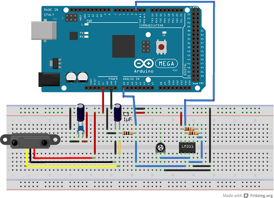
Task 3 – building the Schmitt trigger circuitBuild the schmitt trigger next to the filter built in the previous article as the figure below shows. You may have to tune the potentiometer later to make sure the schmitt trigger triggers properly.
Task 4 – Software harness model and run on targetThe software harness model to be used to run the software on target is shown below.
The analog input block reads pin 0, A0, which is our sensor value. On the lower left is our new interrupt block. The blocks to the right writes to digital pin 12 and 13. There are two extra blocks in this model that could require some explanation. The first is the function-call generator. This is used to trigger the step function periodically. The rate transition block is needed because the source block of the signal, the interrupt service routine, is asynchronous while the digital output block is synchronous with a periodic sample time.
Now try running it on target!
Suggested experiments- Modify and experiment with the schmitt trigger to get desired thresholds. Don’t forget to update the model to match the behavior.
- Test with the detailed model from part 1. Is the small model enough? Are there any differences?
This article shows an example of how to use an asynchronous block in simulation and running on target as an interrupt service routine. This can be useful to save execution time on target and to react to events.
In the next article we are going to use this on a mobile robot. First we will set up a simulator for the robot to test the implementation and then we run the software part on a real robot.
Useful links- Arduino documentation for using interrupts
- Guy and Seth’s blog on creating driver blocks for Arduino etc.


Comments