
Hardware components | ||||||
 |
| × | 1 | |||
 |
| × | 1 | |||
| × | 1 | ||||
Software apps and online services | ||||||
| ||||||
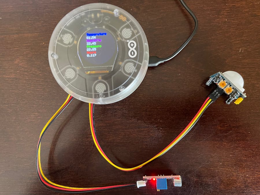
In this project the Arduino Opla with a PIR sensor and sound sensor are used to send environmental and intrusion data to a smart phone or tablet through Blynk. Commands from the smart phone control LEDs and relays on the Opla to activate remote devices.
I was looking for a compact Internet of Things (IoT) device with self-contained temperature, humidity and air pressure sensors that could be remotely located in a hangar with my airplane and send this information to my smart phone. I wanted to be able to detect intrusions into my locked hangar since several people at the airport have a key. I also wanted to be able to remotely turn on/off two different external devices such as an electric engine preheater and light from my smart phone.
I have a Verizon Jet Pack 8800 in my hangar that provides a wifi Internet connection for the Opla since there is no other wifi signal available. The Opla's MKR IoT Carrier has a lot of sensors including temperature, humidity and air pressure. I used the PIR sensor that came with the Opla IoT Kit and an Elegoo microphone sensor to detect intrusions. The Opla has an internal color graphics display which I used to display temperature, humidity, air pressure and run time hours locally when I'm in the hangar. For amusement and experience with the Opla's capabilities I programmed the Opla's buzzer to play the theme from Close Encounters of the Third Kind on startup. Although I started with the Arduino_MKRIoTCarrier All_Features sketch example, I modified it significantly for my needs.
The Opla kit included a Seeed Studios PIR sensor and Grove cable which I used on port A5 of the Opla to sense intrusions. I wanted a sound sensor and I already had a Keyes Microphone Sound Detection Sensor Module for Arduino from an Elegoo sensor kit that runs on 3.5 - 10 volts. The Opla uses 3.3 volts so I needed a microphone sensor that would operate on the lower voltage.
I used code snippets from the Blynk library examples to construct my sketch. I included all of the sensitive wifi and Blynk login information in a separate config.h include file. The Blynk Template ID would not work in the config.h file and had to be included in the sketch, but it wasn't sensitive since it's the standard Quick Start template.
The included libraries were based on the example Blynk sketches used with MKR IoT Carrier and MKR WiFi 1010.
One change that I wanted to make from the example sketch was to find a better way to store and play a tune on the Opla's buzzer. I used a C++ structure to define a note's attributes and included an array of the structure for all the notes in the tune. This was much easier to deal with than the separate include file and duration array used in the example. I looked up the note frequencies on the Internet. It took some experimentation to get the note durations right.
I added three Blynk timer events to the sketch. The Blynk timer.run() method can handle up to 8 timer events of different durations as defined by the timer.setInterval() statements in the setup section of the sketch. Blynk guidelines stress using the timer events rather than delay() statements, which might block the Blynk heartbeat and drop the connection.
The first timer event sends temperature, humidity, pressure and run time data to virtual Blynk pins which display the data in widgets on the Blynk Cloud web template and smart phone Blynk app. This timer event also checks the Opla's pin A5 for a HIGH output on the PIR sensor each time the event is called. If a HIGH is detected, indicating an intrusion, then the sketch writes the HIGH to a Blynk virtual pin that displays as LED widgets on the Blynk Cloud web template and smart phone's Blynk app. The on time and sensitivity of the PIR sensor can be adjusted with two potentiometers on the sensor board. Once triggered, the PIR sensor's output goes HIGH for about 4 seconds. To prevent multiple events from being sent to Blynk Cloud, I included a logic switch variable that inhibits Blynk virtual pin writes for 6 seconds. I used time stamps rather than delays to avoid blocking the Blynk heartbeat.
The second timer event checks for a HIGH from the microphone sensor connected to the Opla on pin A6 on a shorter timer interval of 500 milliseconds so as not to miss briefer events. A separate timer event was needed because the interval was different. Sound events are much shorter in duration than the output of the PIR sensor so the 1 second interval of the first timer event might not catch a sound event. The digital output of the microphone sensor is used rather than the analog output. The sensitivity of the microphone sensor is set by an on-board potentiometer so that the on-board LED and data output are only turned on by louder sounds. To prevent multiple events from being sent to Blynk, I included the same logic switch code that was used on the PIR sensor event.
The third timer event displays the temperature, humidity, air pressure and run time in decimal hours on the Opla's local graphics display every 5 seconds.
Two BLYNK_WRITE() special functions check for and send commands from the Blynk Cloud web template or the Blynk smart phone app to the Opla on virtual pins V0 and V6. One command lights the four Opla LEDs blue and opens/closes Opla relay 1. The other command lights the four Opla LEDs red and opens/closes Opla relay 2. The button widgets on the Blynk Cloud web template and Blynk smart phone app show ON/OFF when the buttons are activated. The Opla relays can control normally open or normally closed external circuits. I would use them to turn on a light on my hangar or an electric engine preheater. The contacts are rated at 24 volts so the relays would have to activate higher voltage relays or solid state devices to control 120 VAC circuits such as an engine preheater.
The main loop in the sketch is minimal as recommended in the Blynk guidelines and only contains Blynk.run() to keep the Blynk heartbeat alive and timer.run() to check and operate the three events.
The function that displays the data on the graphics display controls the position and text color of each line in the display. Pixels stay on once set so it was simpler to erase the entire display and re-write the data every 5 seconds rather than manipulating each line of the display.
The function that plays the tune on the Opla buzzer simply steps through the notes in the array. Rests between notes are entered in the array with a 0 frequency and the appropriate duration.


Comments