I'm currently doing a lot of PCB assembly in work and I find the soldering fumes irritate my eyes and lungs.Using a cheap smoke detector, we can use its piezo buzzer output to drive a MOSFET switched extractor fan. This same design could be used to ventilated a room in the event of a fire or if carbon monoxide is detected!
Parts neededFull parts list in BOM attached.
- P-channel power MOSFET (IRF9530)
- NPN transistor (C549C)
- Battery powered smoke detector (optical or ionisation)
- 9-12V @1A+ power supply or suitable battery
- Bridge rectifier (4x general purpose diodes)
- Assorted capacitors
- Assorted resistors
- Assorted diodes
- Perf board to assemble circuit OR purchase pre-populated PCB
The IC on the board is a Shanghai Belling BL59S10. This IC contains all functions needed to detect smoke, drive the piezoelectric buzzer and handle alarm interconnections.
'Combined with an IR photoelectric chamber, this IC is used todetect smoke through receiving light scattered by tiny smoke particles going into the chamber.When smoke is detected, A burst of alarm sounds are generated by an external piezoelectricbuzzer driven by the push-pull output of this IC.'
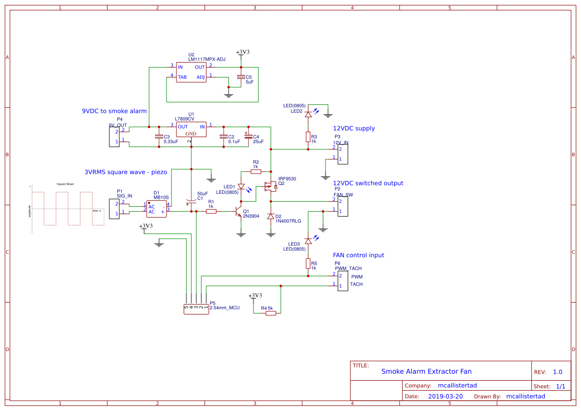
The first step was dismantling the smoke alarm and finding a signal strong enough to switch a transistor on the circuit board. The data sheet indicated an IO connection for auxiliary alarm systems but on probing the signal generated under test/ alarm conditions, the current supplied by a high state was insufficient to drive a transistor without further amplification. It was decided that the square wave oscillator output with a peak to peak voltage of ~6V would be able to drive the external switching circuit. Another benefit of this design is that the circuit is more or less universal, as all smoke alarms drive a piezo-electric buzzer in a similar manner. A full bridge rectifier is used to rectify the oscillator output and maintain saturation under alarm conditions.A flywheel diode is placed across the switched fan output to protect the onboard electronics.
When disconnecting the piezo-electric element, note which wire is the connected to the piezo feedback electrode. This will be left disconnected. Only the input and ground electrodes will be connected to the fan controller.
A 9V voltage regulator is used to supply power from the 12V power supply to the smoke alarm. Alternatively, a 9V smoke alarm battery can be used to power both the fan and the alarm. *Note that some smoke alarm ICs may be 12V tolerant.
The fan driver circuit is a high-side MOSFET switch design, with a common P-channel IRF9530 switching the load. Fan speed can be adjusted using a variable resistor in series with the fan, or with the updated board design by sending a pulse-width modulated signal to the fan from a microcontroller.
PrototypeThe first prototype was assembled on copper strip-board. A 4mm drill bit is used to cut shorts on the copper strips.
Using EDA software (Eagle, KiCAD, EasyEDA) I created a simple PCB designed to occupy as small a footprint as possible and to be easily solderable (all components on topside and 0805 SMD caps/resistors). Screw terminals allow bare wire connections to the board.
- When soldering, first reflow SMD components to the board, then hand solder the through hole components.
The sensitivity of smoke detection can be adjusted by rotating the variable resistor on the smoke alarm circuit board. The system can be tested by pressing the test button for ~1 second.
Finished PCBs- Incorporate a PWM driver circuit to regulate the fixed rotational speed of the extractor fan. Typical computer case fans come with 4 wires - (+12V | 0V | PWM | TACHO) The TACHO output can be used to measure the pulses generated by an internal hall-effect sensor and the PWM input is used to set the fan speed.
- Another tested feature that I plan to develop is a galvanically isolated microcontroller interface. With this, we would have the ability to activate/ disable the fan remotely, log events (time/ duration of smoke detection/ fan on-time) and forward to an IoT platform.


_3u05Tpwasz.png?auto=compress%2Cformat&w=40&h=40&fit=fillmax&bg=fff&dpr=2)
Comments
Please log in or sign up to comment.