We are going to make a Wi-Fi enabled, AWS connected hospital bed occupancy sensor with Thermal IR MEMS sensor.
1. Make a breadboard prototype and use simple code to test the wiring and data transmission with the sensor.
2. Connect the AVR-IoT WA to our AWS account.
3. Flash the firmware to the board.
4. Solder all the components to a perfboard.
5. Put everything in a nice enclosure.
6. Visualise the sensor data using AWS QuickSight.
The ideaDuring the pandemic I was astonished when I found out that local hospitals are using shared spreadsheets to track bed occupancy. As a maker and electronics engineer I told my self that I should find a better solution.
I made a quick research on current generation bed occupancy sensors and 100% of the solutions on the market were based on pressure sensors that are installed under the mattress. I found these solutions far from optimal because of few factors:
- Bed sheets are changed quite often and this can lead to sensor misplacement.
- After few years of usage the pressure sensing elements might get worn out due to friction and mishandling.
- Fixing(replacing) a malfunctioned sensor includes moving the patient to another bed which in some cases is unacceptable.
- All solutions I found were very expensive(250$ and more).
So I thought: there must be a better and simpler solution to this problem.
and voila...
The sensor - Omron D6There comes the Thermal IR MEMS sensor Omron D6T.
Thermal IR MEMS sensors can detect human presence by sensing changes in human body temperature with respect to the surrounding temperature. Think of them as a small thermal camera with few pixels.
The Omron D6T is available with 1 pixel, 8 pixels in 1 row, 4x4 pixels and 32x32 pixels. In this project we are going to use the 1 pixel model.One of the biggest benefits of these sensors over the massively adopted PIR sensors is that they can detect stationary humans(I bet you have found yourself in the dark many times in public toilets). The example below gives a good idea on how both sensors work:
PIR sensor:
Thermal IR MEMS sensor:
Or in other words - Once a PIR sensor detect a person it triggers and if the person stays stationary in the field view of the sensor, the sensor "gets used to" the person and cannot detect its presence unless the person makes a considerable move.
On the other hand, the Thermal IR MEMS sensor is able to detect the person even when stationary because the thermopile element absorbs the radiant energy from the human body(measures its temperature).
However, the Thermal IR MEMS sensors have one drawback - power consumption. The sensor I am going to use for this tutorial consumes 5ma @ 5V. But using proper techniques we can still design a long-lasting battery powered sensor node.
To read the sensor and to upload its readings to the cloud we need a microcontroller with network connectivity.
The brain - AVR-IoT WA by MicrochipIn this project we will be using an amazing development board from Microchip - AVR-IoT WA(WA stands for AWS cloud, there are also versions for other cloud providers) with ATMEGA4808MCU and ATWINC1510 Wi-Fi module.
The main specs of the board include:
- 🕹ATMEGA4808 MCU with onboard PKoB Nano Programmer/Debugger
- 📡ATWINC1510 Wi-Fi Module
- 🔒ATECC608A Secure Element
- 🔋LiPo battery charger
- 🌡MCP9808 Temperature sensor
- 💡Light sensor
!!!This step is very important!!!
Microchip has made a comprehensive guide on this topic. I suggest you to follow the steps carefully and read every sentence. If you did everything as described you will be able to successfully receive the sensor data from the on-board sensors in the test tab of IoT Core.
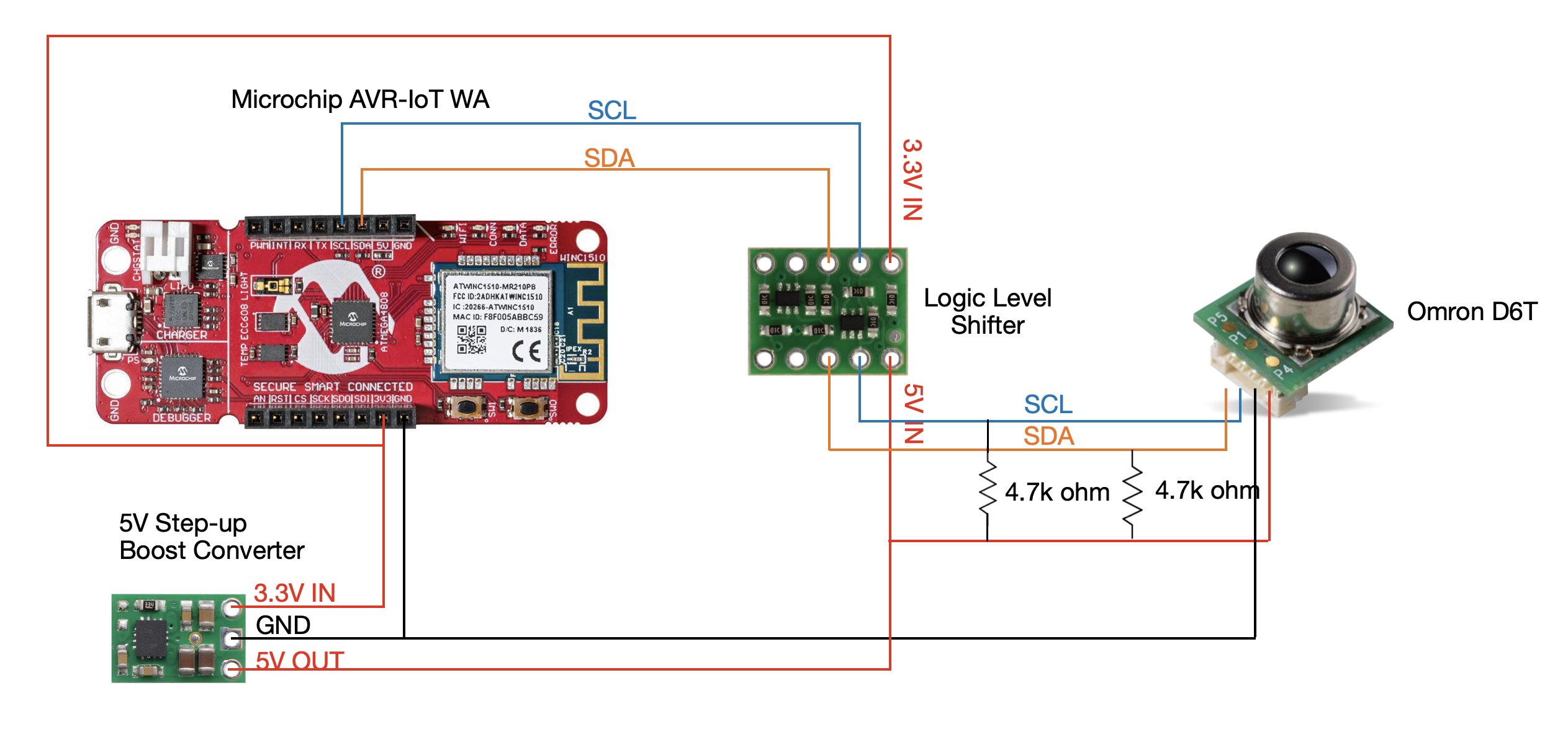
In my setup I have used two half size breadboards glued to a sheet of plastic(so they don't move). On the breadboard we have few components:
- Omron D6T - connected with screw terminals to the breadboard.
- Logic level shifter which converts the 5V signals from the sensor to 3.3V which the MCU can accept and vice versa.
- 2x4.7k Ohm pull-up resistors - Please note that on the photos the pull-up resistors are put on both 5V and 3.3V side(a total of 4). I later discovered that the AVR-IoT has on-board 4.7k Ohm pull-up resistors on the I2C lines. So you only need to put2pull-up resistors on the 5V side for SCL and SDA.
- 5V boost converter - boosts 3.3V supplied by the AVR-IoT to 5V required by the sensor.
Before we begin with this section, we must install Microchip MPLAB X and XC8 Compiler.
When we are ready, we can download the test code from this Github repository and follow the instructions in the video below.
If everything goes right as show in the video and the serial port outputs the temperature reading and the occupancy status, we are good to continue. If not, please check your wiring and make sure you have all the components placed correctly. You can use a multimeter to check your connections and voltages.
PCB and EnclosureOnce we are sure that our breadboard prototype works, we can continue by soldering all the components to a perfboard. We can use any perfboard with 0.01" (2.54mm) distance between the holes.
Before we cut the perfboard, we need to find a suitable enclosure that will be able to fit all the components and the battery. I have chosen this nice white plastic enclosure from the local electronics store.
Once we have a good candidate, we can cut the PCB to fit the enclosure. I have marked the perfboard with a black marker so I can cut it precisely with the saw.
After cutting the board with the saw, I used an electric emery to make the cuts at the edges, but using a saw would also work fine.
Before we continue with soldering, find a good spot for your sensor and make a hole on the enclosure using a drill.
For soldering the headers to small breakout boards like the 5V boost converter, I suggest you to insert the long side of the header into a breadboard and place the breakout board on top. This way you don't need third or fourth hand to solder the header.
When placing the components on the perfboard we should consider the connections between the components and place them in such way that they are as close as possible to one another. Using this approach you can easily make solder traces. This method however need some practicing and if you are not good at soldering you can just solder some thin wires between the components.
Once you are ready with the soldering, clean your perfboard with alcohol - preferably isopropyl alcohol and a brush(soft tooth brush is fine) in order to clean the board from flux and other sticky nasties from the soldering process.
After that take your multimeter and check all connections according to the schematic and make sure that there are no shorts between adjacent pins or traces.
Now that we are sure all connections are fine and there are no shorts, we must run the test firmware again in order to make sure our device is working as expected.
The final device looks like this:
Please watch the video below where I will guide you through the process. We will download the firmware from this Github repository, flash it and test the data reception in AWS IoT Core.
Visualising sensor data in AWS using QuickSightCollecting sensor data without visualising it in a comprehensive way is pointless. This is why we will setup AWS IoT Analytics and AWS QuickSight.
Using QuickSight we can easily create meaningful dashboards that can be viewed on both smartphones(using QuickSight app) and computers. Please watch the video below where I will guide you through the process of setting up AWS IoT Analytics and AWS QuickSight.
Improvement of the hardware part
In order to become a commercial product, some major improvements must be made to the hardware design.Using a better batteryand power management IC
LiPo batteries have high self-discharge rate - 5% for the first 24h and after that 1-2% per month + additional 3% for the protection circuit.
The perfect solution for a battery powered sensor node is a primary lithium battery such as Li-SOCl2 battery coupled with a super capacitor.
Li-SOCL2 batteries have self-discharge rate of 1% per year but discharging them with high currents dramatically decreases their capacity. This is where the super capacitor comes into play.
We can put the whole system in deep sleep mode for 10 to 15 minutes between each sensor reading. During sleep mode we can charge the super capacitor while limiting the current from the battery to no more than 5 mA in order to maintain its health. When the system wakes up, all the energy will be taken from the capacitor. On the other hand, super capacitors are able to supply very high currents which is mandatory when using a Wi-Fi chip because the current spikes can easily go over 300ma @3.3v
For the power management, there are ICs such as Analog Devices - LTC3335 which are design for use with Li-SOCl2 batteries. The LTC3335 can be programmed to limit the current flow from the battery. It also features an integrated Coulomb counter(fuel gauge) for precise measurement of the battery capacity. Knowing the remaining charge of a battery is mandatory for medical IoT devices because it allows for better planning of maintenance operations.
Device firmware and cloud infrastructure
The firmware can also be further improved by implementing energy saving techniques such as deep sleep as mentioned above and powering on the WiFi chip only when there is a change of the occupancy state.
In this tutorial we only laid the foundation in the cloud infrastructure. AWS has great features and is a perfect place to host a robust backend for critical IoT systems. Using AWS we can:
- Store the sensor data in a time-series database.
- Host a web app for device management and real-time monitoring of bed occupancy.
- Generate daily, monthly etc. reports for beds occupancy.
- Host a backend for mobile app(and develop one) to enable doctors and hospital management to easily gain insight on the beds' occupancy.
We live in interesting times. With COVID-19 taking all over the world and millions of people in need of hospital treatment, we - the makers and big corporations should work side by side to implement cutting edge technology in the medical sector.
The doctors are working overtime and the hospitals are full. The least we can do to help the health system is to develop more and more solutions for automation of everyday tasks and processes. Maintaining a register of occupied beds being one of them.
Thank you for reading this tutorial. I hope you have learned something new!


_IHYK2AHej1.png?auto=compress%2Cformat&w=40&h=40&fit=fillmax&bg=fff&dpr=2)


_3u05Tpwasz.png?auto=compress%2Cformat&w=40&h=40&fit=fillmax&bg=fff&dpr=2)
Comments
Please log in or sign up to comment.