


Hardware components | ||||||
 |
| × | 1 | |||
 |
| × | 1 | |||
 |
| × | 1 | |||
 |
| × | 1 | |||
 |
| × | 1 | |||
 |
| × | 1 | |||
 |
| × | 1 | |||
| × | 1 | ||||
| × | 1 | ||||
Software apps and online services | ||||||
 |
| |||||
What if you could create a system to measure the time that your machine was connected with the Arduino? Or measure the time a driver started working after he sat down and got up to leave work?
Systems like these are made using equipment called an hour meter. The hour meter is a piece of equipment that records the start and end times of an event.
From this recorded data, you can monitor an operator's working hours, equipment usage time for future maintenance intervention, and other needs.
In this article, I will teach you exactly how to build an hour meter.
We will use the Arduino, an SD Card, and a DS1307 Real Time Clock.
Next, you'll learn:
- How to configure the DS1307
- How to build the hour meter circuit
- How to communicate Arduino with SD Card
- How to communicate Arduino with RTC
- How to create a light signal to indicate that the system is recording data
This project was developed in partnership with NEXTPCB. Now, you will learn how to build this project.
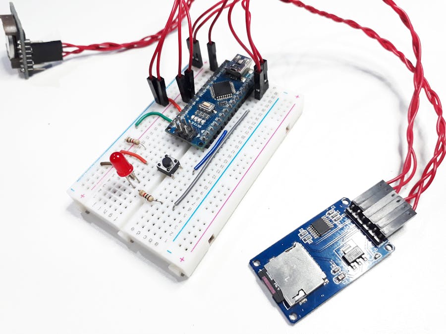
Constructing the projectTo begin, you must build this electronic circuit shown in the figure below.
From the electronic diagram above, you will assemble the circuit shown in the figure below.
After all, how does this project work? This project consists of using a real-time clock to count the hours and an SD Card Module to store the time information in a text file.
The system works as follows: the user must press the button to start recording the time count.
When the button is pressed, the system captures the time, records it on the SD card, and triggers the red LED to indicate that the system is counting the hours.
After completing the activity performed by the user, he must press the button again.
When the button is pressed, the system will register the end time and turn off the LED, to indicate that the time count is stopped.
The code is quite simple and it will be explained below. Next, we’ll explain the main parts of that code.
#include <DS1307.h>
#include <Wire.h> //Biblioteca de Comunicacao I2C
#include <SD.h>
#include <SPI.h>

File myFile;

bool button = 0, state = 0;
byte count = 0;

bool grava = 0;

byte pinoSS = 10; //Pin 10 para UNO

char times[29] = "";
int DataTime[7];

void setup()
{

Serial.begin(9600);
DS1307.begin();

pinMode(pinoSS, OUTPUT); // Declara pinoSS como saída
pinMode(2, INPUT);
pinMode(7, OUTPUT);

Wire.begin(); //Inicializacao da Comunicacao I2C

if(SD.begin())
{
// Inicializa o SD Card
Serial.println("SD Card pronto para uso."); // Imprime na tela
}

else

{
Serial.println("Falha na inicialização do SD Card.");
return;
}
  DS1307.setDate(20,5,19,2,17,23,00);
  DS1307.getDate(DataTime);
}

void loop()
{

  button = digitalRead(2);
  delay(50);

  if(button == 1 && state == 0)
  {
    count++;
    Serial.println(count);
    state = 1;

    if(count == 1)
    {

      if (SD.exists("hour.txt"))
      {
        myFile = SD.open("hour.txt", FILE_WRITE); // Cria / Abre arquivo .txt
        myFile.println("Iniciando tempo de serviço.");
        Serial.println("O arquivo já foi criado!");
      }

      else

      {
        Serial.println("Criou o arquivo!");
        myFile = SD.open("hour.txt", FILE_WRITE); // Cria / Abre arquivo .txt
      }

      delay(500);

      DS1307.getDate(DataTime);

      sprintf(times, "%02d/%02d/%02d - %02d:%02d", DataTime[2], DataTime[1], DataTime[0], DataTime[4], DataTime[5]);
      myFile.println(times);
      Serial.println(times);

      digitalWrite(7, HIGH);
    }

    if(count == 2)
    {
      count = 0;
      Serial.println(count);
      digitalWrite(7, LOW);

      DS1307.getDate(DataTime);

      sprintf(times, "%02d/%02d/%02d - %02d:%02d", DataTime[2], DataTime[1], DataTime[0], DataTime[4], DataTime[5]);
      Serial.println(times);
      myFile.println(times);
      myFile.close();
      Serial.println("Fechou o arquivo!");
    }
  }

  if(button == 0 && state == 1)
  {
    state = 0;
  }


}
First, we declare the RTC and SD Card libraries. Finally, we declare the variables and object of the SD Card, as shown in the code below.
#include <DS1307.h>
#include <Wire.h> //Biblioteca de Comunicacao I2C
#include <SD.h>
#include <SPI.h>

File myFile;

bool button = 0, state = 0;
byte count = 0;

bool grava = 0;

byte pinoSS = 10; //Pin 10 para UNO

char times[29] = "";
int DataTime[7];
After declaring the variables and libraries, we have the setup function.
void setup()
{

Serial.begin(9600);
DS1307.begin();

pinMode(pinoSS, OUTPUT); // Declara pinoSS como saída
pinMode(2, INPUT);
pinMode(7, OUTPUT);

Wire.begin(); //Inicializacao da Comunicacao I2C

if(SD.begin())
{
// Inicializa o SD Card
Serial.println("SD Card pronto para uso."); // Imprime na tela
}

else

{
Serial.println("Falha na inicialização do SD Card.");
return;
}
  DS1307.setDate(20,5,19,2,17,23,00);
  DS1307.getDate(DataTime);
}
In the void setup function, we made the following settings:
- Initialization of the RTC module
- I / O pin configuration
- Initialization of I2C serial communication
- SD Card configuration
- Setting the system date and time
After that, we will enter the void loop function to execute the main logic of the project. The code is shown below.
void loop()
{

  button = digitalRead(2);
  delay(50);

  if(button == 1 && state == 0)
  {
    count++;
    Serial.println(count);
    state = 1;

    if(count == 1)
    {

      if (SD.exists("hour.txt"))
      {
        myFile = SD.open("hour.txt", FILE_WRITE); // Cria / Abre arquivo .txt
        myFile.println("Iniciando tempo de serviço.");
        Serial.println("O arquivo já foi criado!");
      }

      else

      {
        Serial.println("Criou o arquivo!");
        myFile = SD.open("hour.txt", FILE_WRITE); // Cria / Abre arquivo .txt
      }

      delay(500);

      DS1307.getDate(DataTime);

      sprintf(times, "%02d/%02d/%02d - %02d:%02d", DataTime[2], DataTime[1], DataTime[0], DataTime[4], DataTime[5]);
      myFile.println(times);
      Serial.println(times);

      digitalWrite(7, HIGH);
    }

    if(count == 2)
    {
      count = 0;
      Serial.println(count);
      digitalWrite(7, LOW);

      DS1307.getDate(DataTime);

      sprintf(times, "%02d/%02d/%02d - %02d:%02d", DataTime[2], DataTime[1], DataTime[0], DataTime[4], DataTime[5]);
      Serial.println(times);
      myFile.println(times);
      myFile.close();
      Serial.println("Fechou o arquivo!");
    }
  }

  if(button == 0 && state == 1)
  {
    state = 0;
  }


}
The code above is quite simple. The system counts the number of times the button was pressed. If the count value is equal to 1, the system will capture the hour value, record on the SD Card, turn on the LED to signal the hour count.
If the count value is equal to 2, the system will capture the hour value, write to the SD Card, reset the count value and turn off the LED in order to signal that the count is stopped.
The system clears the counting variable to allow it to restart counting when the button is pressed again.
From the operation of this project, a printed circuit board was developed to assemble the hour meter project.
Assembly of the Hourmeter NEXTPCB Printed Circuit BoardFor this project, the PCB presented below was developed. You can use it with an Arduino Nano.
In addition, all modules and buttons are connected to the board in order to facilitate the assembly of the project.
The 3D printed circuit board is presented below.
This printed circuit board was developed from the electronic diagram below.
Finally, we present the structure of the printed circuit board in the 2D view.
If you want to assemble your NEXTPCB Hour Meter, you can download the files and purchase your test plates for free at NEXTPCB.
AcknowledgmentSilício Lab thanks to the support of NEXTPCB for offering free test PCB's for the assembly of this project. You can also obtain your test PCB's at NEXTPCB.


Comments
Please log in or sign up to comment.