This project emulates a Philips Hue Bridge that is able to control Hue lights (using original Hue Bridge), IKEA Tradfri lights (usign Tradfri Bridge), Mi-Light bulbs (using MiLight Hub), Neopixel strips (WS2812B and SK6812) and any cheep ESP8266 based bulb from market by replacing firmware with custom one. Is written in python and will run on all small boxes like RaspberryPi. There are provided sketches for Hue Dimmer Switch, Hue Tap Switch and Hue Motion Sensor. Lights are two-way synchronized so any change made from original Philips/Tradfri sensors and switches will be applied also to bridge emulator.
- python
- nmap package for lights autodiscover
sudo apt install namp
- On/Off control for other home devices using virtual lights
- Alarm horn based on esp8266
- Control lights (all functions)
- Control groups (all functions)
- Scenes (all functions)
- Routines
- Wake up
- Go to sleep
- Switches (custom esp8266 switches)
- Motion sensor
- Autodiscover lights
- Home & Away futures (require remote api that is not public)
Open http://{bridgeIP}/hue, type the bridge ip and before to click "Save" press the link button on the Hue Bridge. The total number of lights copied to Bridge Emulator will be displayed.
IKEA TRADFRIOpen http://{bridgeIP}/tradfri, type Ikea bridge ip and security key and click "Save". If everything was fine you will see all lights paired with Tradfri bridge in Hue application. Important: coap-client-linux binary is compiled for arm devices like raspberry pi. If you will use an x86 computer then you will need to recompile this.
MI-LIGHT:esp8266_milight_hub is required https://github.com/sidoh/esp8266_milight_hub. Open http://{bridgeIP}/milight, complete the form and click Save. You need to repet this step for every light as there is no way to retrieve the list of lights from milight hub.
Is possible to convert MiLight bulbs to wifi using any ESP8266 module. I convert one RGB-CCT bulb with ESP-12S module (picture available) in less than 30 minutes. From original board you will need just the 3.3v regulator (not recommended because of low power) and the led drivers (NPN transistors for colored leds, MOSFET for white leds) + nearby resistors that are connected to transistors base/gate, other components can be disconnected/removed, mandatory disconnect the IC that control the leds because will enter in conflict with ESP module. I connect GPIO12/13/14 to resistors that point to the base of RGB transistors and GPIO4/5 directly to MOSFET gates (not thru resistors because these are connected to ground). For stability an extra capacitor is required on power line.
Wi-fi connection is setup using WiFiManager https://github.com/tzapu/WiFiManager so you must connect to wifi named "New Hue Light" and open in browser http://192.168.4.1/ to setup the connection to your wifi network. There is support for both WS2812B (rgb) and SK6812 (rgbw) smart leds (neopixels). Data in pin of the strip must be connected to rx pin of esp8266 device. In order to compile the sketch you must download NeoPixelBus (by Makuna) and WiFiManager (by tzapu) libraries available in Arduino library manager. Is possible to emulate more lights in one strip by setting lightsCount value to any value. I recommend about 3 lights per strip in order to have nice scenes.
GENERIC PWM LIGHTS:
Most of wifi bulbs and strip controllers from the market are esp8266 based and control the brightness of leds using pwm. The only real difference from them is the number/order of the output pins. You will find sketches for almost all typesof bulbs: cct, rgb, rgbw, rgb_cct. If you intend to buy some cheap wifi bulbs/strips and want to use this project you will need to check how hard is to flash the firmware in that light. So far i use only "Color Dreams" wifi bulbs and i was able to flash the firmware with external serial adapter (check github issue #26) .
Options in skeches:
lightsCount x//number of emulated lights per strip, available only for neopixels stript
pixelCount xx// number of leds in strip, available only for neopixels strips
IPAddress strip_ip ( xxx, xxx, xxx, xxx);//if you want to use static ip uncommented with gateway_ip, subnet_mask and WiFi.config(strip_ip, gateway_ip, subnet_mask) line. lights can be controlled from internal GUI or with hue api via http GET of POST. example url:
"http://{light ip}/set?light=1&r=0&g=60&b=255&transitiontime=2000"
"http://{light ip}/discover"
list of arguments that can be passed in url:
- "on": 1 to set light on, 0 to set the light off.
- "r", "g", "b": setup light color using rbg values between 0 and 255.
- "x" and "y": values between 0.0 and 1.0 to setup light color in CIE chart.
- "ct": value between 153 (max warm white) and 500 (max could white) http://en.wikipedia.org/wiki/Mired
- hue: value between 0 and 65535, represent the hue of the light.
- sat: saturation of the light. 255 is the most saturated and 0 is the least saturated.
- bri: brightness of the light, 255 is the maximum brightness, 1 is the minimum, 0 will turn the light on to previews state
- transitiontime: duration of the transition from the light’s current state to the new stat. default 4 represent 0.4 seconds.
- bri_inc: uncrease or decrease the brightness with a specified value
SWITCHES:
Dimmer Switch and Tap Switch are almost identical, the only difference is that dimmer switch can control the lights also without the bridge (for this reason bridgeIp is declared as array to setup more ip's), and the buttons codes are different.
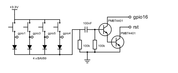
On sensor power on there will be a GET request sent to bridge , ex: http://{bridgeIP}/switch?mac=xx:xx:xx:xx:xx:xx&devicetype=ZLLSwitch. Bridge will check based on mac address if the switch is already registered or not. If not it will register and then it will be available for configuration in Hue application. After 3-5 seconds ESP8266 will enter in deep sleep mode and will consume less than 20uA. On every button press there will be a short negative pulse on ESP8266 RST pin that will wake up the device, read input pins to check what button is pressed and send a request like this: http://{bridgeIP}/switch?mac=xx:xx:xx:xx:xx:xx&button=1000. Bridge will process all rules and perform the action configured for this button.
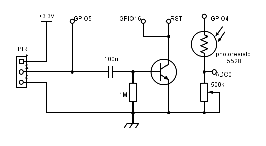
MOTION SENSOR:How is working:Exactly like switches the sensor will be registered on power on with GET request http://{bridgeIP}/switch?mac=xx:xx:xx:xx:xx:xx&devicetype=ZLLPresence and configuration will be done from Hue application. ESP8266 will wake up from deep sleep on every PIR positive signal on GPIO5 pin and at every 20 minutes to send light sensor data. Request example: http://{bridgeIP}/switch?mac=xx:xx:xx:xx:xx:xx&lightlevel=46900&dark=false&daylight=true&presence=true. Is important to choose a low power PIR that can run on batteries for many months. The PIR used in my example is HC-SR501, most common used in DIY projects. To increase the battery life i remove the voltage regulator to 3.3V because this become useless on batteries. GPIO4 will output +3V only when light level is measured to lower power consumption.
ALARM
Is possible to receive email notification when one motion sensor is triggered while alarm is active. To configure the alarm you must first edit the file alarm_config.json and add your smtp credentials. On first execution HueEmulator.py will send a test email and if this is successful sent a new virtual light named "Alarm" will be automatically created. You will need to create a dummy room to control this virtual light. Turn this light on/off to enable/disable the alarm.


Comments
Please log in or sign up to comment.