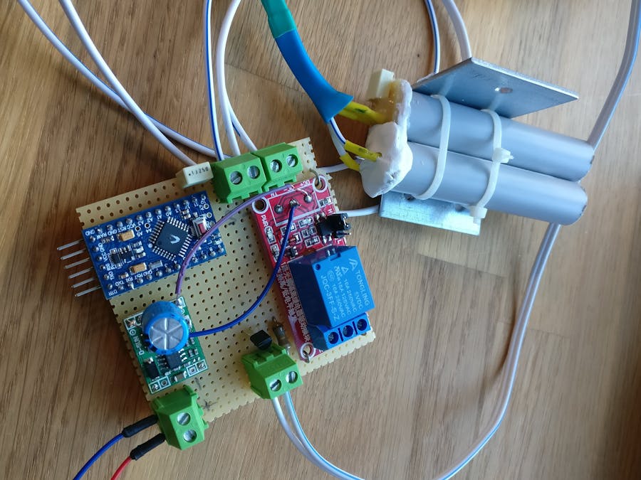
- I found These LEDs with a half-angle of 5 degrees able to emit 100mA of power. They also emit light at 940nm which is perfect for the receiver.
- Vishay TSSP4038 IR receiver. The receiver is made to detect continuous 38kHz light also. Some other sensors need bursts which I weren't ready to figure out how to code.
- Arduino Pro Mini 3.3v
- D-SUN adjustable voltage regulator. I just had it lying around
- 5V Relay module able to be triggered by the 3.3V Arduino
- 0.1uF Capacitor
- 300uF capacitor
- 2N7000 transistor (This one can only handle 200mA so that limits the power for the LEDs but it's still more than the 20mA the Arduino pin can output) Might want to upgrade to a 2N2222 instead if more power is needed.
I've gathered bits and pieces from other projects to make this. The coding could probably be nicer looking and so could the soldering. But hey, it works.
I wanted to make a sensor with no dedicated transmitter but a reflector panel instead. Also, it needed to be long-range. It's fairly easy to find these on ebay but pretty damn difficult to find any with a range of about 15m which I need. So I built one...
I had a lot of trouble getting this thing working but two things I learned were that the capacitor near the sensor is a MUST and that light pollution is a bitch. I ended up covering the whole sensor in Sugru (except the front, obviously) to keep stray light out. It's pretty difficult to see that annoying IR light but I realised that it travelled through the plastic PCB-ish material. The Sugru did it.
Final results first:Actually, after testing my first setup I discovered that the effective range was only around 10m.
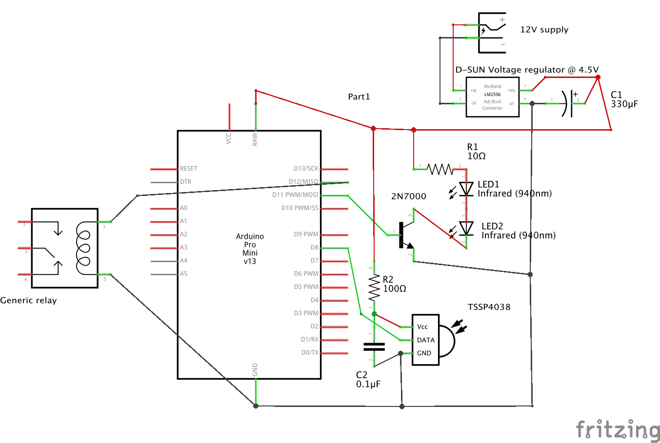
In order to increase the range I tried ramping up the effect on the LEDs. So I turned the voltage regulator up from the previous 3.3v to around 4.5v AND supplied the Arduino via the RAW pin instead of the VCC pin in order to utilise the onboard regulator here. I put in a 10 Ohm resistor in series with the LEDs. (depicted on the schematics) I then discovered that my Arduino had a handicap and it's voltage regulator was dead. So I switched it to a Trinket Pro 3v I had lying around. Basically the same functionality between the two.
Functioning:The built-in timer function on the Arduino works on pin 11 and connects to the gate on the transistor in order for the LEDs to pull more than the 20mA the Arduino can directly supply. My LEDs can safely pull 100mA at 1.5V CONTINUOUS. When pulsing this can be safely increased to roughly 160mA according the spec sheet (page 4, lower left corner).
The IR receiver is connected to power (via a resistor) and has as 0.1uF capacitor (very important, apparently). The output from the receiver connected to pin 8 goes low when it detects 38kHz modulated IR light and high when the beam is broken. Very easy to program the Arduino around.
Pin 12 is connected to a relay module also powered from the external voltage regulator by 4.5V
The coding makes sure that whenever the beam is broken the onboard LED lights up. This is mainly for aiming the sensor at the reflector. Only when the beam has been broken for 2 secs pin 12 will go high and trigger the relay. This is because I want people (and cars) to be able to move through the beam without triggering it. Only if a car is PARKED the relay goes off. This coding could most likely be prettier but I copy/pasted/edited from other projects, one using a push button to trigger different things for long/short presses.


_3u05Tpwasz.png?auto=compress%2Cformat&w=40&h=40&fit=fillmax&bg=fff&dpr=2)
Comments
Please log in or sign up to comment.