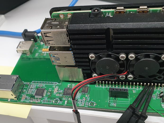
Last year, I was working on a project using a Raspberry Pi. More than 100 Raspberry Pis have been installed in hard-to-reach places, and a few devices have experienced system hangs due to system errors or heat.
So I needed a device that can monitor and reset the Raspberry Pi, and I designed a circuit to monitor the Raspberry Pi by referring to the data of W5100s-EVB-Pico released this time.
Hardware DesignThe hardware configuration is as shown in the figure above.
The input power must be supplied with DC12V 2A or more, and an external LTE router (2Port) that uses 5V 2A is used.
The reason why the Raspberry Pi power supply is 3A is that the current consumption of the Raspberry Pi is large when driving AI models. When it was around 2A, it sometimes caused problems. Sufficiently sufficient supply current is required.
It measures the state of supplying power to the pico ADC through a 12V voltage divider circuit. The range is marked with the expectation of 9~12V.
Pico ADC_AVDD is configured using the LM4040 as instructed in the Raspberry Pi datasheet.
Raspberry Pi 40 pin header circuit.
The pico-side power control EN is controlled by pin 13 and connected to the pico using UART0. You can download FW from Raspberry Pi to Pico using SWD.
Pico's UART and Raspberry Pi are connected, and power EN is controlled by GPIO #6.
For the rest of the Pico circuit, refer to the W5100s-EVB-PICO circuit.


_xcg7vos8ax_LjVH1Q6mKB.png?auto=compress%2Cformat&w=48&h=48&fit=fill&bg=ffffff)


Comments
Please log in or sign up to comment.