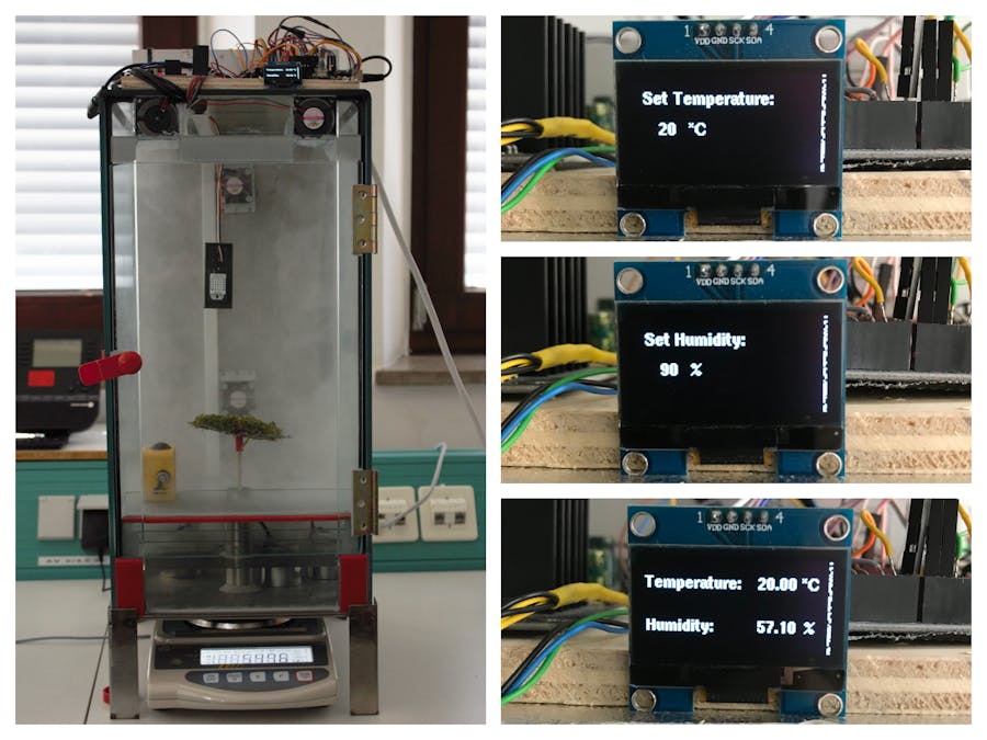
Being ecologists, we investigate organisms and their responses to natural conditions, such as variations in temperature (T) and relative humidity (RH). Sometimes it is unfavorable or simply impossible to conduct experiments on site. Additionally, it is advantageous to be able to simulate whatever conditions are desired, regardless of a right timing; as changing seasons or weather conditions might foil a plan. Also, this system could be used to pretest to know what to expect as an outcome or to validate the functionality of materials, which will be used in field. Planned experiments can be performed withoutdelay.
Our system is constructed on low-costs and could be recreated by anyone. We set the skill level to advance, because assembly requires manual dexterity and more than basic household tools, especially wiring also requires solid knowledge of electrical engineering. In contrast the coding for this project is quiet simple.
Here, we present the prototype of a climate chamber system, which was designed and constructed to perform gravimetric experiments under differing humidity conditions. So far, the option to manipulate the temperature state wasn't used, neither tested. Nonetheless, we include the devices of temperature control in our system description and the wiring.
System description and structureThe main structure is a second-hand aquarium, of the size of 49 cm x 34 cm x 25 cm. It is positioned upright, so that the aquarium bottom corresponds to the posterior wall of the chamber. Following, the named posterior wall and bottom of the chamber were each replaced by a 3 mm metal plate. Since metal has a higher thermal diffusivity, the metal plates should accelerate the distribution of cold and warmth inside the chamber, when cooling or heating is activated. The glass pane that originally served as the bottom of the aquarium was converted into a door to allow the chamber to be opened and closed. The climate chamber is positioned on top of a 10 cm high metal frame to enable positioning of devices with moisture sensitive electronics outside the system. To reach the interior of the chamber a metal pipe is integrated in the construction of the bottom plate (see detailed view above).
The electronic components include three ultrasonic nebulisers placed on the bottom as humidity sources and two peltier elements integrated into the posterior wall, as well as two heat beds installed at the bottom, to regulate temperature. For air circulation throughout the chamber, two fans are placed at the top of the anterior plane.
System circuit and connectionsAll of the electronics are wired on top of the machinery. The small MOSFETs are actuated by the control signal (5V) of the Arduino microcontroller, which then forward the signal (12V) to the high power MOSFETs, while one triggers the fans directly. In the latter case, the signal originating from the microcontroller uses Pulse Width Modulation (PWM) to regulate the revolutions per minute of the fan (750-3000 rpm). The high power MOSFETs are powered by the Power Adapter and are used for switching the subsequent devices, such as the peltier elements, the heat beds and the nebulisers. In the circuit of the nebulisers, two transformers are connected between the power supply and the high power MOSFETs to reduce the voltage from 12V (30A) to 24V (1A). The thermistors, display, encoder and T/RH sensor are powered directly by the power of the microcontroller, which itself is powered by the power adapter.
ProgrammingAgain, we didn't use temperature control yet. That's why our code only includes switching of the nebulisers.
We use an Arduino Uno R3 to handle the climate control. To program the Arduino microcontroller as a controller for the climate chamber, we need to install special header files:
First, we decide for a desired relative humidity level between 30-100% humidity, using the rotary encoder. With each clockwise rotation the value changes +5, counterclockwise -5, pressing confirms the value shown in the display as the desired one. Be aware, we can only increase humidity inside the chamber by switching on the nebulisers, thus we cannot achieve values lower than those in the surrounding environment.
Our set point is then compared to the actual relative humidity level measured by the DHT22 inside the chamber. If the measured level is lower the nebulisers are switched on to moisten the air. The fans are running permanently to assure air circulation, allowing for distribution of the water droplets throughout the chamber. When the desired humidity level is reached, the program logic continues reading the actual humidity level, while the nebulisers stay off.
You can find our code for humidity control in the Code Section below.


_ztBMuBhMHo.jpg?auto=compress%2Cformat&w=48&h=48&fit=fill&bg=ffffff)


Comments
Please log in or sign up to comment.