In Arduino PWM Tutorial, you are going to learn about what PWM is and how you can get the PWM output from the digital pins of Arduino. First, we will control thebrightness of LED through code and then we will control it manually by adding the potentiometer.
For Custom Projects, hire me at https://www.freelancer.com/u/Muhammadaqibdutt
What is PWMPWM stands for Pulse Width Modulation and it is a technique used in controlling the brightness of LED, speed control of DC motor, controlling a servo motor or where you have to get analog output with digital means.
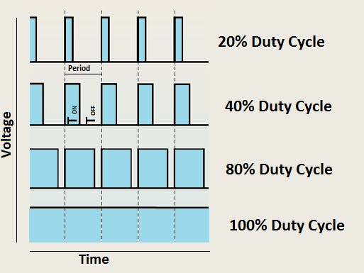
The Arduino digital pins either gives us 5V (when turned HIGH) or 0V (when turned LOW) and the output is a square wave signal. So if we want to dim a LED, we cannot get the voltage between 0 and 5V from the digital pin but we can change the ON and OFF time of the signal. If we will change the ON and OFF time fast enough then the brightness of the led will be changed.
Before going further, let’s discuss some terms associated with PWM.
TON (On Time): It is the time when the signal is high.
TOFF (Off Time): It is the time when the signal is low.
Period: It is the sum of on time and off time.
Duty Cycle: It is the percentage of time when the signal was high during the time of period.
So at 50% duty cycle and 1Hz frequency, the led will be high for half a second and will be low for the other half second. If we increase the frequency to 50Hz (50 times ON and OFF per second), then the led will be seen glowing at half brightness by the human eye.
The Arduino IDE has a built in function “analogWrite()” which can be used to generate a PWM signal. The frequency of this generated signal for most pins will be about 490Hz and we can give the value from 0-255 using this function.
analogWrite(0) means a signal of 0% duty cycle.
analogWrite(127) means a signal of 50% duty cycle.
analogWrite(255) means a signal of 100% duty cycle.
On Arduino Uno, the PWM pins are 3, 5, 6, 9, 10 and 11. The frequency of PWM signal on pins 5 and 6 will be about 980Hz and on other pins will be 490Hz. The PWM pins are labeled with ~ sign.
Controlling Brightness of LED through CodeFirstly, make the connections as described below.
Connect the positive leg of LED which is the longer leg to the digital pin 6 of Arduino. Then connect the 220 ohm resistor to the negative leg of LED and connect the other end of resistor to the ground pin of Arduino.
Read More: Interfacing LED with Arduino
Now let’s write a code to change the brightness of the LED using PWM.
Arduino CodeUpload the code in the Arduino IDE and the LED will start to fade.
//Initializing LED Pin
int led_pin = 6;
void setup() {
  //Declaring LED pin as output
  pinMode(led_pin, OUTPUT);
}
void loop() {
  //Fading the LED
  for(int i=0; i<255; i++){
    analogWrite(led_pin, i);
    delay(5);
  }
  for(int i=255; i>0; i--){
    analogWrite(led_pin, i);
    delay(5);
  }
}In the previous connections, add the 10k ohm potentiometer and connect the two ends of potentiometer to 5V and GND of Arduino and then connect the center of potentiometer to the A0 pin of Arduino.
Upload the code in the Arduino IDE and on moving the knob of the potentiometer, the brightness of the LED will change.
int led_pin = 6;
int pot_pin = A0;
int output;
int led_value;
void setup() {
  pinMode(led_pin, OUTPUT);
}
void loop() {
  //Reading from potentiometer
  output = analogRead(pot_pin);
  //Mapping the Values between 0 to 255 because we can give output
  //from 0 -255 using the analogwrite funtion
  led_value = map(output, 0, 1023, 0, 255);
  analogWrite(led_pin, led_value);
  delay(1);
}
Also Read:
- How to control an LED with button using Arduino
- How to build an Arduino Traffic Light Controller
- Density based traffic light controller using Arduino
If you have any questions, feel free to ask in the comment section.


_ztBMuBhMHo.jpg?auto=compress%2Cformat&w=48&h=48&fit=fill&bg=ffffff)


Comments
Please log in or sign up to comment.